


'%3e%3cpath%20d='M10%2010.5V17h12.5v5.5l-21%20.038V15l8.5-4.5ZM1%206h11M6.5%202H12M5.5%2022.5V19'/%3e%3cpath%20d='M21.21%2017.012%2020.14%201.5h-4.28l-1.07%2015.512M15.516%206.49h4.967'/%3e%3c/g%3e%3cdefs%3e%3cclipPath%20id='a'%3e%3cpath%20fill='%23fff'%20d='M0%200h24v24H0z'/%3e%3c/clipPath%3e%3c/defs%3e%3c/svg%3e)











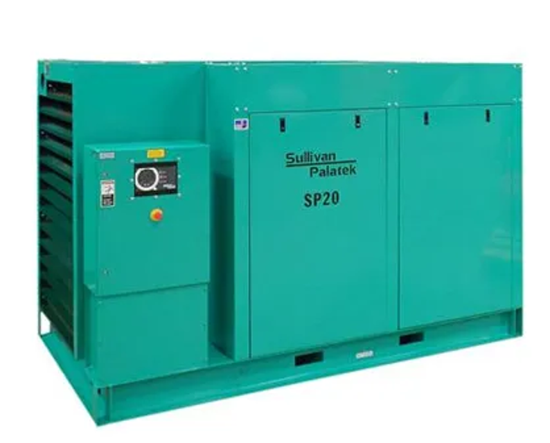
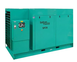
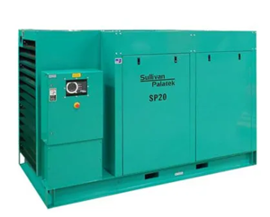
Sullivan-Palatek Industrial Air Compressor SP20-250
Need answers fast?
Explore the manual using AI.
Turn manuals into instant answers
with your AI-powered assistantTurn manuals into instant answers
with your AI-powered assistant
Manual for Sullivan-Palatek Industrial Air Compressor SP20-250
Complete asset maintenance, one click away
Get instant access to all the maintenance information you need. Empower technicians to perform preventive maintenance with asset packages, ready to use right out of the box.

Documents & Manuals
Find all the essential guides in one place.
 Tensioning Guide
- Belt-diagram
- C-120 pulleys
+ 13 more

Work Order Templates
Pre-built workflows to keep your asset running smoothly.
- Daily Electrical System Inspection
- Replace Roller and Pulley
- Install Engine B-120
+ 29 more

Procedures
Integrate maintenance plans directly into your work orders.
- Motion Industries
- Applied Industrial Technologies
- Electrical Brothers
+ 5 more

Parts
Access the parts list for your equipment in MaintainX.
- Drive Motor
- B2 Rollers
- Tensioning System
+ 40 more
Sullivan-Palatek Industrial Air Compressor SP20-250
Create an account to install this asset package.
Maintenance Plans for Sullivan-Palatek Industrial Air Compressor Model SP20-250
Integrate maintenance plans directly into your work orders in MaintainX.
1000 Hourly / 3 Monthly Oil Filter Replacement
The oil filter should be replaced after the first 50 hours of operation and then every 1,000 hours (or quarterly) or if fault A:2020 or A:4807 is shown on the microprocessor.
The fluid filter is located between the thermal valve and the unit injection port. The SP models have the filter mounted with the filter elements located on the top side. Once the pressure in the system has been completely depleted, most of if not all of the fluid in the elements have drained out making replacement simpler.
The following procedures should be followed before doing any maintenance on the compressor and will not be repeated in any of the maintenance procedures.
1. Per Occupational Safety & Health Administration (OSHA) regulation 1910.147: The Control of Hazardous Energy Source (Lockout/Tagout), disconnect and lockout the main power source. Display a sign in clear view at the main power switch stating that the compressor is being serviced.
2. Isolate the compressor from the compressed air supply by closing a manual shutoff valve downstream from the compressor. Display a sign in clear view at the shutoff valve that the compressor is being serviced. Be certain that a pressure relief valve is installed upstream of any isolation valve.
3. Wait until sump pressure reading is 0 psig.
4. Open all manual drain valves within the area to be serviced.
5. Wait for the unit to cool before starting to service. Temperatures of 125°F (52°C) can burn skin. Some surface temperatures exceed 250°F (121°C) when the compressor is operating and just after it is shut down.
REMOVAL:

1 Daily Compressor Check
Observe control panel
Check for leaks
Inspect return line flow, Correct as needed
Note: Compressor running fully loaded;
1 Daily Compressor Lubricant Level Check
Instructions for checking the compressor lubricant level
Shut down the compressor (or check before the compressor is turned on)
Wait two minutes after the compressor stops to allow the pressure to be relieved and the oil to settle
Observe the oil level in the fluid sightglass. The fluid sightglass should be full
While the compressor is running, the oil should be visible in the sightglass and the compressor not running hot
Note: Checked with compressor off - sightglass full. Checked while running - any level in sightglass and unit not running hot.
Sign off on the daily compressor lubricant level check
2000 Hourly Air Filter Replacement
The air filter should be replaced every 2,000 hours or more often in severe or outside conditions or if fault A:2030 or A:4804 is shown on the microprocessor.
The inlet filter is a critical filter, protecting the compressor from exterior foreign materials. Keeping the inlet filter element clean will help maintain proper capacity rating of the compressor.
The following procedures should be followed before doing any maintenance on the compressor and will not be repeated in any of the maintenance procedures.
1. Per Occupational Safety & Health Administration (OSHA) regulation 1910.147: The Control of Hazardous Energy Source (Lockout/Tagout), disconnect and lockout the main power source. Display a sign in clear view at the main power switch stating that the compressor is being serviced.
2. Isolate the compressor from the compressed air supply by closing a manual shutoff valve downstream from the compressor. Display a sign in clear view at the shutoff valve that the compressor is being serviced. Be certain that a pressure relief valve is installed upstream of any isolation valve.
3. Wait until sump pressure reading is 0 psig.
4. Open all manual drain valves within the area to be serviced.
5. Wait for the unit to cool before starting to service. Temperatures of 125°F (52°C) can burn skin. Some surface temperatures exceed 250°F (121°C) when the compressor is operating and just after it is shut down.
REMOVAL:
4000 Hourly / 1 Yearly Separator Element Replacement
The separator element should be replaced every 4,000 hours (or once a year) or if fault E:0809, A:2808 or A:4806 is shown on the microprocessor.
Refer to Figure 6-5. The separator element is located in the top side of the sump tank under the tank lid. To replace the element, access panels have been supplied in the roof. By opening the enclosure roof, overhead access and external light is available.
The following procedures should be followed before doing any maintenance on the compressor and will not be repeated in any of the maintenance procedures.
1. Per Occupational Safety & Health Administration (OSHA) regulation 1910.147: The Control of Hazardous Energy Source (Lockout/Tagout), disconnect and lockout the main power source. Display a sign in clear view at the main power switch stating that the compressor is being serviced.
2. Isolate the compressor from the compressed air supply by closing a manual shutoff valve downstream from the compressor. Display a sign in clear view at the shutoff valve that the compressor is being serviced. Be certain that a pressure relief valve is installed upstream of any isolation valve.
3. Wait until sump pressure reading is 0 psig.
4. Open all manual drain valves within the area to be serviced.
5. Wait for the unit to cool before starting to service. Temperatures of 125°F (52°C) can burn skin. Some surface temperatures exceed 250°F (121°C) when the compressor is operating and just after it is shut down.
REMOVAL:
Parts for Sullivan-Palatek Industrial Air Compressor SP20-250
Access the parts list for your equipment in MaintainX.
Adapter, 1.5 O-Ring X 1.25
0093000-2024
Adapter, 1.5"O-Ring X 1.25SAE
03000-2024
Adapter, Inlet 204 TO Air-Con 6IN
03000-024
Adapter, MTR/COMP 204 A/E
01240-152
Adapter, Oil Return Orifice
00023-001
Adapter, 1.5 O-Ring X 1.25
0093000-2024
Adapter, 1.5"O-Ring X 1.25SAE
03000-2024
Adapter, Inlet 204 TO Air-Con 6IN
03000-024
Adapter, MTR/COMP 204 A/E
01240-152
Adapter, Oil Return Orifice
00023-001
Adapter, 1.5 O-Ring X 1.25
0093000-2024
Adapter, 1.5"O-Ring X 1.25SAE
03000-2024
Adapter, Inlet 204 TO Air-Con 6IN
03000-024
Adapter, MTR/COMP 204 A/E
01240-152
Adapter, Oil Return Orifice
00023-001
Unlock efficiency
with MaintainX CoPilot
MaintainX CoPilot is your expert colleague, on call 24/7, helping your team find the answers they need to keep equipment running.
'%20stroke-width='2.05034'/%3e%3cpath%20d='M43.601%2020.8897C43.2688%2019.252%2042.7312%2017.6627%2042.001%2016.1597'%20stroke='url(%23paint1_linear_4912_14668)'%20stroke-width='2.05034'/%3e%3cpath%20d='M40.001%2012.8882C38.8627%2011.3731%2037.516%2010.0265%2036.001%208.88818'%20stroke='url(%23paint2_linear_4912_14668)'%20stroke-width='2.05034'/%3e%3cpath%20d='M32.729%206.89053C31.2266%206.1604%2029.638%205.62282%2028.001%205.29053'%20stroke='url(%23paint3_linear_4912_14668)'%20stroke-width='2.05034'/%3e%3cpath%20d='M24.001%2014.8901V24.8901L32.001%2032.8901'%20stroke='url(%23paint4_linear_4912_14668)'%20stroke-width='2.05034'/%3e%3cdefs%3e%3clinearGradient%20id='paint0_linear_4912_14668'%20x1='4'%20y1='25'%20x2='44'%20y2='25'%20gradientUnits='userSpaceOnUse'%3e%3cstop%20stop-color='%23246CFF'/%3e%3cstop%20offset='1'%20stop-color='%232ED888'/%3e%3c/linearGradient%3e%3clinearGradient%20id='paint1_linear_4912_14668'%20x1='3.5'%20y1='20.8897'%20x2='44'%20y2='20.8897'%20gradientUnits='userSpaceOnUse'%3e%3cstop%20stop-color='%23246CFF'/%3e%3cstop%20offset='1'%20stop-color='%232ED888'/%3e%3c/linearGradient%3e%3clinearGradient%20id='paint2_linear_4912_14668'%20x1='3.5'%20y1='12.8882'%20x2='44.5'%20y2='12.8882'%20gradientUnits='userSpaceOnUse'%3e%3cstop%20stop-color='%23246CFF'/%3e%3cstop%20offset='1'%20stop-color='%232ED888'/%3e%3c/linearGradient%3e%3clinearGradient%20id='paint3_linear_4912_14668'%20x1='6.5'%20y1='6.89053'%20x2='43.5'%20y2='6.89053'%20gradientUnits='userSpaceOnUse'%3e%3cstop%20stop-color='%23246CFF'/%3e%3cstop%20offset='1'%20stop-color='%232ED888'/%3e%3c/linearGradient%3e%3clinearGradient%20id='paint4_linear_4912_14668'%20x1='5'%20y1='32.8901'%20x2='44'%20y2='32.8901'%20gradientUnits='userSpaceOnUse'%3e%3cstop%20stop-color='%23246CFF'/%3e%3cstop%20offset='1'%20stop-color='%232ED888'/%3e%3c/linearGradient%3e%3c/defs%3e%3c/svg%3e)
Reduce Unplanned Downtime
Ensure your team follows consistent procedures to minimize equipment failures and costly delays.
'%20stroke-width='2.05034'/%3e%3cpath%20d='M46.667%2041.7231C46.667%2044.5079%2045.5607%2047.1786%2043.5916%2049.1478C41.6225%2051.1169%2038.9518%2052.2231%2036.167%2052.2231C33.3822%2052.2231%2030.7115%2051.1169%2028.7424%2049.1478C26.7732%2047.1786%2025.667%2044.5079%2025.667%2041.7231C25.667%2038.9384%2026.7732%2036.2677%2028.7424%2034.2985C30.7115%2032.3294%2033.3822%2031.2231%2036.167%2031.2231C38.9518%2031.2231%2041.6225%2032.3294%2043.5916%2034.2985C45.5607%2036.2677%2046.667%2038.9384%2046.667%2041.7231Z'%20stroke='url(%23paint1_linear_4912_14680)'%20stroke-width='2.05034'/%3e%3cpath%20d='M37.334%2035.8896V40.5563H42.0007'%20stroke='url(%23paint2_linear_4912_14680)'%20stroke-width='2.05034'/%3e%3cdefs%3e%3clinearGradient%20id='paint0_linear_4912_14680'%20x1='5'%20y1='52.2231'%20x2='51'%20y2='52.2231'%20gradientUnits='userSpaceOnUse'%3e%3cstop%20stop-color='%23246CFF'/%3e%3cstop%20offset='1'%20stop-color='%232ED888'/%3e%3c/linearGradient%3e%3clinearGradient%20id='paint1_linear_4912_14680'%20x1='5'%20y1='52.2231'%20x2='47'%20y2='52.2231'%20gradientUnits='userSpaceOnUse'%3e%3cstop%20stop-color='%23246CFF'/%3e%3cstop%20offset='1'%20stop-color='%232ED888'/%3e%3c/linearGradient%3e%3clinearGradient%20id='paint2_linear_4912_14680'%20x1='5'%20y1='40.5563'%20x2='52.5'%20y2='40.5563'%20gradientUnits='userSpaceOnUse'%3e%3cstop%20stop-color='%23246CFF'/%3e%3cstop%20offset='1'%20stop-color='%232ED888'/%3e%3c/linearGradient%3e%3c/defs%3e%3c/svg%3e)
Maximize Asset Availability
Keep your assets running longer and more reliably, with standardized maintenance workflows from OEM manuals.
'%20stroke-width='2.05034'/%3e%3cpath%20d='M13.9995%2024.2231C13.9995%2029.1738%2015.9662%2033.9217%2019.4669%2037.4224C22.9675%2040.9231%2027.7155%2042.8897%2032.6662%2042.8897C37.6169%2042.8897%2042.3648%2040.9231%2045.8655%2037.4224C49.3662%2033.9217%2051.3328%2029.1738%2051.3328%2024.2231C51.3328%2019.2724%2049.3662%2014.5244%2045.8655%2011.0237C42.3648%207.52306%2037.6169%205.5564%2032.6662%205.5564C27.7155%205.5564%2022.9675%207.52306%2019.4669%2011.0237C15.9662%2014.5244%2013.9995%2019.2724%2013.9995%2024.2231Z'%20stroke='url(%23paint1_linear_4912_14674)'%20stroke-width='2.05034'/%3e%3cpath%20d='M32.6665%2017.2231V12.5564'%20stroke='url(%23paint2_linear_4912_14674)'%20stroke-width='2.05034'/%3e%3cpath%20d='M32.6665%2035.8898V31.2231'%20stroke='url(%23paint3_linear_4912_14674)'%20stroke-width='2.05034'/%3e%3cpath%20d='M37.9165%2020.7231V19.5565C37.9165%2018.9376%2037.6707%2018.3441%2037.2331%2017.9066C36.7955%2017.469%2036.202%2017.2231%2035.5832%2017.2231H29.7498C29.131%2017.2231%2028.5375%2017.469%2028.0999%2017.9066C27.6623%2018.3441%2027.4165%2018.9376%2027.4165%2019.5565V20.6018C27.4166%2021.1326%2027.5977%2021.6475%2027.9298%2022.0615C28.262%2022.4756%2028.7254%2022.764%2029.2435%2022.8791L36.0895%2024.4005C36.6077%2024.5157%2037.071%2024.8041%2037.4032%2025.2181C37.7353%2025.6321%2037.9164%2026.147%2037.9165%2026.6778V28.8898C37.9165%2029.5086%2037.6707%2030.1021%2037.2331%2030.5397C36.7955%2030.9773%2036.202%2031.2231%2035.5832%2031.2231H29.7498C29.131%2031.2231%2028.5375%2030.9773%2028.0999%2030.5397C27.6623%2030.1021%2027.4165%2029.5086%2027.4165%2028.8898V27.7231'%20stroke='url(%23paint4_linear_4912_14674)'%20stroke-width='2.05034'/%3e%3cdefs%3e%3clinearGradient%20id='paint0_linear_4912_14674'%20x1='5'%20y1='33.5'%20x2='50'%20y2='33.5'%20gradientUnits='userSpaceOnUse'%3e%3cstop%20stop-color='%23246CFF'/%3e%3cstop%20offset='1'%20stop-color='%232ED888'/%3e%3c/linearGradient%3e%3clinearGradient%20id='paint1_linear_4912_14674'%20x1='5'%20y1='42.8897'%20x2='48.5'%20y2='42.8897'%20gradientUnits='userSpaceOnUse'%3e%3cstop%20stop-color='%23246CFF'/%3e%3cstop%20offset='1'%20stop-color='%232ED888'/%3e%3c/linearGradient%3e%3clinearGradient%20id='paint2_linear_4912_14674'%20x1='5'%20y1='17.2231'%20x2='52.5'%20y2='17.2231'%20gradientUnits='userSpaceOnUse'%3e%3cstop%20stop-color='%23246CFF'/%3e%3cstop%20offset='1'%20stop-color='%232ED888'/%3e%3c/linearGradient%3e%3clinearGradient%20id='paint3_linear_4912_14674'%20x1='3.5'%20y1='35.8898'%20x2='50.5'%20y2='35.8898'%20gradientUnits='userSpaceOnUse'%3e%3cstop%20stop-color='%23246CFF'/%3e%3cstop%20offset='1'%20stop-color='%232ED888'/%3e%3c/linearGradient%3e%3clinearGradient%20id='paint4_linear_4912_14674'%20x1='3'%20y1='31.2231'%20x2='52'%20y2='31.2231'%20gradientUnits='userSpaceOnUse'%3e%3cstop%20stop-color='%23246CFF'/%3e%3cstop%20offset='1'%20stop-color='%232ED888'/%3e%3c/linearGradient%3e%3c/defs%3e%3c/svg%3e)
Lower Maintenance Costs
Turn any technician into an expert to streamline operations, maintain more assets, and reduce overall costs.
Thousands of companies manage their assets with MaintainX

'%3e%3cpath%20fill='url(%23b)'%20d='M66.008%2080.068c-5.084-.786-9.763-3.834-12.442-8.68a16.942%2016.942%200%200%201-1.87-5.18c1.096.19%202.203.476%203.298.87%206.525%202.333%2010.836%207.68%2011.014%2012.99ZM51.47%2061.576c.488-5.524%203.62-10.716%208.847-13.597a17.132%2017.132%200%200%201%2011.335-1.882c-.798%208.145-7.43%2014.848-16.038%2015.599-1.417.119-2.799.07-4.144-.12Zm28.564-11.478a17.513%2017.513%200%200%201%203.727%204.62c4.608%208.335%201.584%2018.813-6.75%2023.409a16.988%2016.988%200%200%201-4.359%201.679%2019.624%2019.624%200%200%201-3.977-12.776c.346-7.561%204.942-13.931%2011.36-16.932Z'/%3e%3cpath%20fill='%23110F0D'%20fill-rule='evenodd'%20d='M142.831%2048.324h4.977V77.03h-4.977V48.324Zm27.278%2013.002c.322%201.048.453%202.263.453%203.62v12.073h-4.787V66.208c0-.75-.047-1.572-.154-2.143-.453-2.382-1.822-3.572-4.215-3.572-2.31%200-3.882%201.274-4.43%203.476-.143.596-.226%201.405-.226%202.25v10.8h-4.787V56.623h4.477v2.989c1.536-2.5%203.906-3.43%206.371-3.43%203.488%200%206.263%201.68%207.298%205.144Zm24.636%207.323c0%203.882-2.358%206.525-5.763%207.727-1.298.453-2.632.643-4.62.643h-10.169V48.324h9.085c1.691%200%203.156.143%204.049.38%203.465.93%205.727%203.68%205.727%207.335%200%202.441-.81%204.156-2.762%205.644%202.905%201.417%204.453%203.727%204.453%206.966Zm-15.634-8.656h4.584c1.024%200%201.917-.143%202.536-.417%201.215-.548%201.905-1.608%201.905-3.167%200-1.548-.643-2.572-1.845-3.132-.691-.31-1.762-.452-2.763-.452h-4.417v7.168Zm10.716%208.465c0-1.536-.893-3.37-3.227-3.893-.428-.095-1.036-.143-1.571-.143h-5.918v8.085h5.501c.56%200%201.429-.048%201.953-.167%201.94-.453%203.262-1.846%203.262-3.882Zm47.747-11.847-8.097%2020.408h-4.429l-8.109-20.408h5.191l5.192%2014.574%205.108-14.574h5.144Zm-20.218%2010.002c0%20.69-.036%201.262-.155%201.94h-15.943c.631%202.87%202.714%204.728%205.882%204.728%202.131%200%203.607-.882%204.703-2.525h4.87c-1.762%204.144-5.204%206.692-9.657%206.692-6.084%200-10.537-4.858-10.537-10.49%200-6.108%204.524-10.776%2010.335-10.776%206.239%200%2010.442%204.954%2010.502%2010.43Zm-4.763-1.405c-.333-2.846-2.643-4.858-5.691-4.858-2.894%200-5.287%201.929-5.621%204.858h11.312Zm-72.667%203.44c0%204.787-3.287%208.371-9.419%208.371H119.363V64.66c-1.917.274-3.87.69-5.811%201.238l4.537%2011.121h-5.418l-3.596-9.585c-5.144%202.084-10.085%205.216-14.217%209.585h-4.786L101.8%2048.312h4.56l5.68%2013.883a44.112%2044.112%200%200%201%207.323-1.774V48.312h9.084c1.703%200%203.156.143%204.061.393%203.453.929%205.727%203.667%205.727%207.323%200%201.917-.738%204.179-2.81%205.691%203.06%201.56%204.501%204.025%204.501%206.93Zm-15.634-8.667a62.664%2062.664%200%200%201%202.06-.036c1.703.012%203.239.131%204.608.37%201.441-.549%202.357-1.727%202.357-3.537%200-1.941-.881-3.144-2.488-3.667-.548-.18-1.358-.286-2.322-.286h-4.215v7.156Zm-16.55%203.905-3.715-9.894-6.394%2016.502c2.833-2.595%206.263-4.858%2010.109-6.608Zm27.254%204.74c0-2.775-3.131-4.347-8.513-4.418-.715%200-1.441.011-2.191.047v8.252h5.918c2.548%200%204.786-1.37%204.786-3.882Z'%20clip-rule='evenodd'/%3e%3c/g%3e%3cdefs%3e%3clinearGradient%20id='b'%20x1='51.47'%20x2='85.916'%20y1='62.946'%20y2='62.946'%20gradientUnits='userSpaceOnUse'%3e%3cstop%20stop-color='%23CD9F28'/%3e%3cstop%20offset='1'%20stop-color='%23ECD80B'/%3e%3c/linearGradient%3e%3cclipPath%20id='a'%3e%3cpath%20fill='%23fff'%20d='M51.47%2045.728h186.104V80.14H51.47z'/%3e%3c/clipPath%3e%3c/defs%3e%3c/svg%3e)











More from Sullivan-Palatek
Explore Other Assets



© 2026 MaintainX. All rights reserved.