


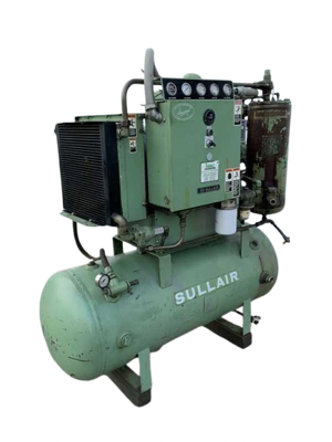
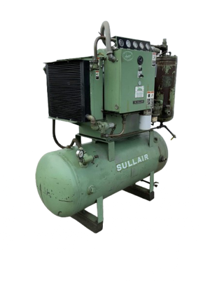
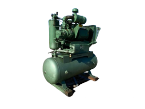
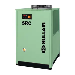
Sullair Sullair Air-Cooled Compressor 10B 25HP-251332-004 AC 10B 25HP-251332-004 AC
Need answers fast?
Explore the manual using AI.
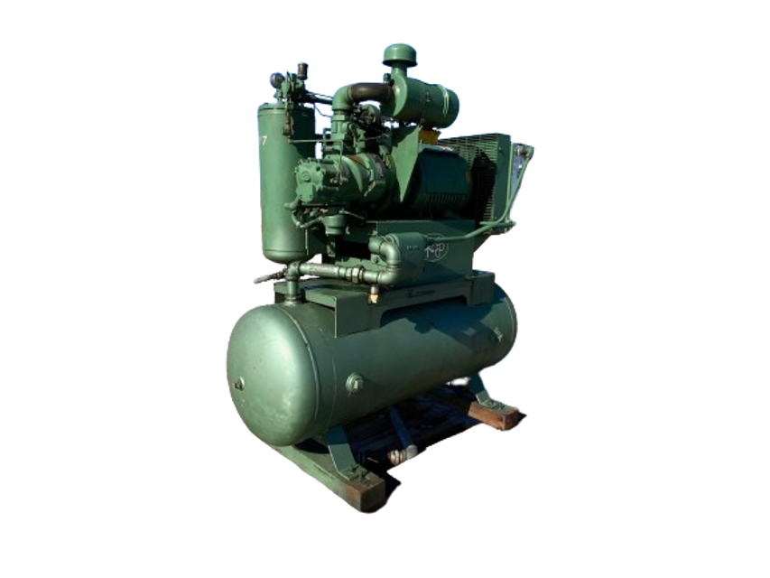
The Sullair Air-Cooled Compressor 10B 25HP-251332-004 AC is a reliable industrial compressor designed for efficient air delivery. Known for its durability and performance, this model is ideal for various applications requiring compressed air solutions. Ensure optimal operation with regular maintenance and quality spare parts.
Turn manuals into instant answers
with your AI-powered assistantTurn manuals into instant answers
with your AI-powered assistant
Complete asset maintenance, one click away
Get instant access to all the maintenance information you need. Empower technicians to perform preventive maintenance with asset packages, ready to use right out of the box.

Documents & Manuals
Find all the essential guides in one place.
 Tensioning Guide
- Belt-diagram
- C-120 pulleys
+ 13 more

Work Order Templates
Pre-built workflows to keep your asset running smoothly.
- Daily Electrical System Inspection
- Replace Roller and Pulley
- Install Engine B-120
+ 29 more

Procedures
Integrate maintenance plans directly into your work orders.
- Motion Industries
- Applied Industrial Technologies
- Electrical Brothers
+ 5 more

Parts
Access the parts list for your equipment in MaintainX.
- Drive Motor
- B2 Rollers
- Tensioning System
+ 40 more
Sullair Sullair Air-Cooled Compressor 10B 25HP-251332-004 AC 10B 25HP-251332-004 AC
Create an account to install this asset package.
Maintenance Plans for Sullair Sullair Air-Cooled Compressor 10B 25HP-251332-004 AC Model 10B 25HP-251332-004 AC
Integrate maintenance plans directly into your work orders in MaintainX.
Compressor Control System Maintenance
Warning: This procedure requires trained personnel with PPE!
Adjust Control System with a desired operating range of 115 to 125 PSIG (792 to 862kPa).
Enter the current operating range
FOR PRESSURE RANGE ADJUSTMENT:
Remove cover to pressure switch
Turn the range adjusting screw to the high pressure setting. Turning the screw counterclock-wise lowers both the high and low pressure equally
FOR DIFFERENTIAL ADJUSTMENT:
Turn the differential adjusting screw to the lower (reset) setting. Turning the screw counterclock- wise widens the differential by lowering the reset (lower) setting only
When the pressure switch adjustment is complete, the pressure regulator should be adjusted for the pressure at which modulation of air delivery should begin.

Compressor Minimum Pressure/ Check Valve Maintenance
WARNING: Before performing maintenance on the valve, be sure that all pressure has been relieved in the compressor sump, and all downstream pressure has been vented to the atmosphere. Also be sure that the components of the compressor are cool to the touch
Unscrew the minimum pressure/check valve (P/N 241581) from the receiver cover
Remove the hexagonal retaining cap from the main body
Remove the flat washer and heavy spring from the main body
Tap the piston assembly (with a screwdriver) from the bottom of the main body and remove. The o-ring will now be seen easily
Remove the seal ring and discard
Clean piston assembly and valve thoroughly
Replace seal ring and coat the piston and seal with Parker Super “O” Ring Seal or an equivalent quality grease
WARNING: Extreme caution should be used when removing the cap from the body because there is spring tension on the cap
Compressor Maintenance
PIPE END PREPARATION
Deburr and clean the pipe ends
The pipe ends are free of all deep scratches, gouges, dents, etc.
JOINT INSTALLATION
Install the retainer (1), gasket (2), and sleeve (3) on one side of the pipe as shown in Step 1
Install the remaining retainer (4) and gasket (5) on the other pipe end
Position the retainer (4) and gasket to proper pipe insertion depth (“D”)
Slide the sleeve (3) to the gasket (5) and move gasket (2) and retainer (1) into position as shown in Step 2. The pipe MUST be inserted to the proper depth (“D”) into both gaskets
COUPLER INSTALLATION
6 Monthly Air Filter Element Replacement
Clean exterior of air filter housing
Remove the air filter cover by loosening the wingnut securing the cover
Remove element and clean interior of housing using a damp cloth. DO NOT blow dirt out with compressed air
Clean or replace the element
Replace cover
Reset the filter maintenance indicator
Sign off on the air filter element replacement
Compressor Thermal Valve Maintenance
Warning: This maintenance check requires trained personnel with PPE!
Remove the appropriate piping from the thermal valve housing
Remove the four (4) capscrews holding the housing together and separate the upper housing from the lower housing
Remove element
Remove and replace the element seal in the upper housing
Remove and replace the o-ring between the upper and lower housings
Replace element
Re-assemble the housing
Sign off on the thermal valve maintenance
Parts for Sullair Sullair Air-Cooled Compressor 10B 25HP-251332-004 AC 10B 25HP-251332-004 AC
Access the parts list for your equipment in MaintainX.
Solenoid Valve
250017–993
Flexible Coupling
250007–544
Air Inlet Valve
250025–654
Repair Kit
250025–621
Blowdown Valve
250025–655
Solenoid Valve
250017–993
Flexible Coupling
250007–544
Air Inlet Valve
250025–654
Repair Kit
250025–621
Blowdown Valve
250025–655
Solenoid Valve
250017–993
Flexible Coupling
250007–544
Air Inlet Valve
250025–654
Repair Kit
250025–621
Blowdown Valve
250025–655
Unlock efficiency
with MaintainX CoPilot
MaintainX CoPilot is your expert colleague, on call 24/7, helping your team find the answers they need to keep equipment running.
Reduce Unplanned Downtime
Ensure your team follows consistent procedures to minimize equipment failures and costly delays.
Maximize Asset Availability
Keep your assets running longer and more reliably, with standardized maintenance workflows from OEM manuals.
Lower Maintenance Costs
Turn any technician into an expert to streamline operations, maintain more assets, and reduce overall costs.
Thousands of companies manage their assets with MaintainX

'%3e%3cpath%20fill='url(%23b)'%20d='M66.008%2080.068c-5.084-.786-9.763-3.834-12.442-8.68a16.942%2016.942%200%200%201-1.87-5.18c1.096.19%202.203.476%203.298.87%206.525%202.333%2010.836%207.68%2011.014%2012.99ZM51.47%2061.576c.488-5.524%203.62-10.716%208.847-13.597a17.132%2017.132%200%200%201%2011.335-1.882c-.798%208.145-7.43%2014.848-16.038%2015.599-1.417.119-2.799.07-4.144-.12Zm28.564-11.478a17.513%2017.513%200%200%201%203.727%204.62c4.608%208.335%201.584%2018.813-6.75%2023.409a16.988%2016.988%200%200%201-4.359%201.679%2019.624%2019.624%200%200%201-3.977-12.776c.346-7.561%204.942-13.931%2011.36-16.932Z'/%3e%3cpath%20fill='%23110F0D'%20fill-rule='evenodd'%20d='M142.831%2048.324h4.977V77.03h-4.977V48.324Zm27.278%2013.002c.322%201.048.453%202.263.453%203.62v12.073h-4.787V66.208c0-.75-.047-1.572-.154-2.143-.453-2.382-1.822-3.572-4.215-3.572-2.31%200-3.882%201.274-4.43%203.476-.143.596-.226%201.405-.226%202.25v10.8h-4.787V56.623h4.477v2.989c1.536-2.5%203.906-3.43%206.371-3.43%203.488%200%206.263%201.68%207.298%205.144Zm24.636%207.323c0%203.882-2.358%206.525-5.763%207.727-1.298.453-2.632.643-4.62.643h-10.169V48.324h9.085c1.691%200%203.156.143%204.049.38%203.465.93%205.727%203.68%205.727%207.335%200%202.441-.81%204.156-2.762%205.644%202.905%201.417%204.453%203.727%204.453%206.966Zm-15.634-8.656h4.584c1.024%200%201.917-.143%202.536-.417%201.215-.548%201.905-1.608%201.905-3.167%200-1.548-.643-2.572-1.845-3.132-.691-.31-1.762-.452-2.763-.452h-4.417v7.168Zm10.716%208.465c0-1.536-.893-3.37-3.227-3.893-.428-.095-1.036-.143-1.571-.143h-5.918v8.085h5.501c.56%200%201.429-.048%201.953-.167%201.94-.453%203.262-1.846%203.262-3.882Zm47.747-11.847-8.097%2020.408h-4.429l-8.109-20.408h5.191l5.192%2014.574%205.108-14.574h5.144Zm-20.218%2010.002c0%20.69-.036%201.262-.155%201.94h-15.943c.631%202.87%202.714%204.728%205.882%204.728%202.131%200%203.607-.882%204.703-2.525h4.87c-1.762%204.144-5.204%206.692-9.657%206.692-6.084%200-10.537-4.858-10.537-10.49%200-6.108%204.524-10.776%2010.335-10.776%206.239%200%2010.442%204.954%2010.502%2010.43Zm-4.763-1.405c-.333-2.846-2.643-4.858-5.691-4.858-2.894%200-5.287%201.929-5.621%204.858h11.312Zm-72.667%203.44c0%204.787-3.287%208.371-9.419%208.371H119.363V64.66c-1.917.274-3.87.69-5.811%201.238l4.537%2011.121h-5.418l-3.596-9.585c-5.144%202.084-10.085%205.216-14.217%209.585h-4.786L101.8%2048.312h4.56l5.68%2013.883a44.112%2044.112%200%200%201%207.323-1.774V48.312h9.084c1.703%200%203.156.143%204.061.393%203.453.929%205.727%203.667%205.727%207.323%200%201.917-.738%204.179-2.81%205.691%203.06%201.56%204.501%204.025%204.501%206.93Zm-15.634-8.667a62.664%2062.664%200%200%201%202.06-.036c1.703.012%203.239.131%204.608.37%201.441-.549%202.357-1.727%202.357-3.537%200-1.941-.881-3.144-2.488-3.667-.548-.18-1.358-.286-2.322-.286h-4.215v7.156Zm-16.55%203.905-3.715-9.894-6.394%2016.502c2.833-2.595%206.263-4.858%2010.109-6.608Zm27.254%204.74c0-2.775-3.131-4.347-8.513-4.418-.715%200-1.441.011-2.191.047v8.252h5.918c2.548%200%204.786-1.37%204.786-3.882Z'%20clip-rule='evenodd'/%3e%3c/g%3e%3cdefs%3e%3clinearGradient%20id='b'%20x1='51.47'%20x2='85.916'%20y1='62.946'%20y2='62.946'%20gradientUnits='userSpaceOnUse'%3e%3cstop%20stop-color='%23CD9F28'/%3e%3cstop%20offset='1'%20stop-color='%23ECD80B'/%3e%3c/linearGradient%3e%3cclipPath%20id='a'%3e%3cpath%20fill='%23fff'%20d='M51.47%2045.728h186.104V80.14H51.47z'/%3e%3c/clipPath%3e%3c/defs%3e%3c/svg%3e)


More from Sullair


Explore Other Assets


© 2025 MaintainX. All rights reserved.