


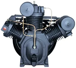
Ingersoll Rand Air Compressor ups-40-125bp
Need answers fast?
Explore the manual using AI.
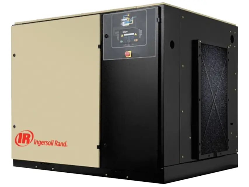
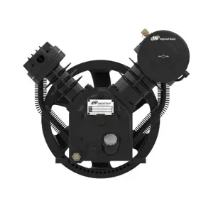
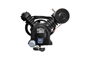
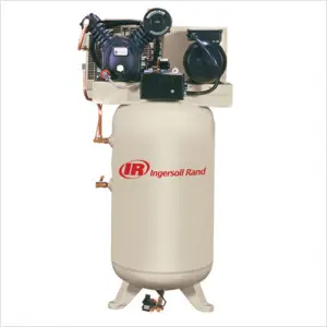
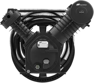
The Ingersoll Rand Air Compressor UPS-40-125BP is a robust industrial compressor designed for high efficiency and reliability. Ideal for various applications, this model ensures optimal air delivery and performance, making it a preferred choice for professionals seeking durable and effective compressed air solutions.
Turn manuals into instant answers
with your AI-powered assistantTurn manuals into instant answers
with your AI-powered assistant
Manual for Ingersoll Rand Air Compressor ups-40-125bp
Complete asset maintenance, one click away
Get instant access to all the maintenance information you need. Empower technicians to perform preventive maintenance with asset packages, ready to use right out of the box.

Documents & Manuals
Find all the essential guides in one place.
 Tensioning Guide
- Belt-diagram
- C-120 pulleys
+ 13 more

Work Order Templates
Pre-built workflows to keep your asset running smoothly.
- Daily Electrical System Inspection
- Replace Roller and Pulley
- Install Engine B-120
+ 29 more

Procedures
Integrate maintenance plans directly into your work orders.
- Motion Industries
- Applied Industrial Technologies
- Electrical Brothers
+ 5 more

Parts
Access the parts list for your equipment in MaintainX.
- Drive Motor
- B2 Rollers
- Tensioning System
+ 40 more
Ingersoll Rand Air Compressor ups-40-125bp
Create an account to install this asset package.
Maintenance Plans for Ingersoll Rand Air Compressor Model ups-40-125bp
Integrate maintenance plans directly into your work orders in MaintainX.
Moisture Separator Maintenance
Isolate the housing from the air supply
Fully depressurize in drain bowl
Unscrew bowl and remove
If pressure has not been completely released from the housing, air will escape from the warning hole giving an audible alarm. Screw back bowl and repeat instruction 2 before attempting again.
Check condition of bowl seal and replace if necessary
Clean screw threads
Refit bowl with ‘O’ ring seal
Repressurize and check for leaks
If leaks occur they will most probably be from the bowl ‘O’ ring. Depressurize housing and remove ‘O’ ring as stated above and inspect and clean. Ensure that mating surfaces are clean and then refit ‘O’ ring and repressurize.

1 Yearly / 2000 Hourly Air Compressor Maintenance
- Change the coolant filter.
Procedure:
1. Stop the machine, electrically isolate and vent all trapped pressure.
2. Loosen filter with the correct tool.
3. Remove the filter from the housing.
4. Place the old filter in a sealed bag and dispose of in a safe way.
5. Clean the mating face of the housing taking care to avoid any particles entering the machine.
6. Remove the new Ingersoll Rand replacement filter from its protective package.
7. Apply a small amount of lubricant to the filter seal.
2 Yearly / 8000 Hourly Air Compressor Maintenance
- Change drive belt and gas spring.
Procedure:
1. Stop the machine, electrically isolate and vent all trapped pressure.
2. Remove the side cover from the machine.
3. Fit a 1/2” square drive wrench in the tension cam located above the airend (access from front door). Turn clockwise 1/4 turn to Position II to release gas strut tension on the belts.
4. Using a small screwdriver under the spring clip, ease the ball ends off the spherical studs at the ends of the gas strut.
5. Replace the gas strut and the studs at the same time by removing and replacing the studs then pushing the new gas strut firmly onto the studs until it clicks into place.
6. Turn the tension cam clockwise 1/4 turn to Position III to raise and support the airend. Place a block of wood or similar under the separator tank for support.
7. Replace the belts from the left side of the machine.
1 Monthly / 100 Hourly Air Compressor Maintenance
- Remove and clean package pre–filter, replace if needed.
- Check the cooler(s) for build up of foreign matter. Clean if necessary by blowing out with air or by pressure washing.
Cleaning Procedure:
1. Stop the machine, electrically isolate and vent all trapped pressure.
2. Remove the top cover to obtain access to the cooler.
3. Clean the cooler.
4. Rebuild in reverse order.
- Check hoses and fittings for leaks – tighten as required.;
Modulate Control Valve Adjustment
Ensure that the compressor is isolated from the compressed air system by closing the isolation valve and venting pressure from the drip leg.
Ensure that the main power disconnect switch is locked open and tagged.
Put the compressor in the MODULATION mode by placing control selector switch SS in the “MODULATION” position (Non–Intellisys models).
Remove 1/4” plastic plug from the tee (18) in the regulator valve Connect a pressure gauge to this port.
Loosen the adjustment screw locknut and back out adjusting screw 3 turns See Figure 2.
Put the main power disconnect switch in the ON position.
Open the isolation valve and start the compressor.
Adjust the isolation valve to bring the discharge air pressure to the rated discharge pressure (100, 125, 140, or 200 psig).
While maintaining the rated discharge pressure, turn the adjustment screw on the modulation valve (see Figure 2) so that the test pressure gauge reads: 30 psig for modulate 60% cfm.
Parts for Ingersoll Rand Air Compressor ups-40-125bp
Access the parts list for your equipment in MaintainX.
Decal, Facia – Intellisys
81295891
Decal, Coolant Drain
93166460
Decal, Notice Rotation
30286686
Decal, Voltage 380/3/60
32236481
Decal, Maintenance Schedule
81296196
Decal, Facia – Intellisys
81295891
Decal, Coolant Drain
93166460
Decal, Notice Rotation
30286686
Decal, Voltage 380/3/60
32236481
Decal, Maintenance Schedule
81296196
Decal, Facia – Intellisys
81295891
Decal, Coolant Drain
93166460
Decal, Notice Rotation
30286686
Decal, Voltage 380/3/60
32236481
Decal, Maintenance Schedule
81296196
Unlock efficiency
with MaintainX CoPilot
MaintainX CoPilot is your expert colleague, on call 24/7, helping your team find the answers they need to keep equipment running.
Reduce Unplanned Downtime
Ensure your team follows consistent procedures to minimize equipment failures and costly delays.
Maximize Asset Availability
Keep your assets running longer and more reliably, with standardized maintenance workflows from OEM manuals.
Lower Maintenance Costs
Turn any technician into an expert to streamline operations, maintain more assets, and reduce overall costs.
Thousands of companies manage their assets with MaintainX

'%3e%3cpath%20fill='url(%23b)'%20d='M66.008%2080.068c-5.084-.786-9.763-3.834-12.442-8.68a16.942%2016.942%200%200%201-1.87-5.18c1.096.19%202.203.476%203.298.87%206.525%202.333%2010.836%207.68%2011.014%2012.99ZM51.47%2061.576c.488-5.524%203.62-10.716%208.847-13.597a17.132%2017.132%200%200%201%2011.335-1.882c-.798%208.145-7.43%2014.848-16.038%2015.599-1.417.119-2.799.07-4.144-.12Zm28.564-11.478a17.513%2017.513%200%200%201%203.727%204.62c4.608%208.335%201.584%2018.813-6.75%2023.409a16.988%2016.988%200%200%201-4.359%201.679%2019.624%2019.624%200%200%201-3.977-12.776c.346-7.561%204.942-13.931%2011.36-16.932Z'/%3e%3cpath%20fill='%23110F0D'%20fill-rule='evenodd'%20d='M142.831%2048.324h4.977V77.03h-4.977V48.324Zm27.278%2013.002c.322%201.048.453%202.263.453%203.62v12.073h-4.787V66.208c0-.75-.047-1.572-.154-2.143-.453-2.382-1.822-3.572-4.215-3.572-2.31%200-3.882%201.274-4.43%203.476-.143.596-.226%201.405-.226%202.25v10.8h-4.787V56.623h4.477v2.989c1.536-2.5%203.906-3.43%206.371-3.43%203.488%200%206.263%201.68%207.298%205.144Zm24.636%207.323c0%203.882-2.358%206.525-5.763%207.727-1.298.453-2.632.643-4.62.643h-10.169V48.324h9.085c1.691%200%203.156.143%204.049.38%203.465.93%205.727%203.68%205.727%207.335%200%202.441-.81%204.156-2.762%205.644%202.905%201.417%204.453%203.727%204.453%206.966Zm-15.634-8.656h4.584c1.024%200%201.917-.143%202.536-.417%201.215-.548%201.905-1.608%201.905-3.167%200-1.548-.643-2.572-1.845-3.132-.691-.31-1.762-.452-2.763-.452h-4.417v7.168Zm10.716%208.465c0-1.536-.893-3.37-3.227-3.893-.428-.095-1.036-.143-1.571-.143h-5.918v8.085h5.501c.56%200%201.429-.048%201.953-.167%201.94-.453%203.262-1.846%203.262-3.882Zm47.747-11.847-8.097%2020.408h-4.429l-8.109-20.408h5.191l5.192%2014.574%205.108-14.574h5.144Zm-20.218%2010.002c0%20.69-.036%201.262-.155%201.94h-15.943c.631%202.87%202.714%204.728%205.882%204.728%202.131%200%203.607-.882%204.703-2.525h4.87c-1.762%204.144-5.204%206.692-9.657%206.692-6.084%200-10.537-4.858-10.537-10.49%200-6.108%204.524-10.776%2010.335-10.776%206.239%200%2010.442%204.954%2010.502%2010.43Zm-4.763-1.405c-.333-2.846-2.643-4.858-5.691-4.858-2.894%200-5.287%201.929-5.621%204.858h11.312Zm-72.667%203.44c0%204.787-3.287%208.371-9.419%208.371H119.363V64.66c-1.917.274-3.87.69-5.811%201.238l4.537%2011.121h-5.418l-3.596-9.585c-5.144%202.084-10.085%205.216-14.217%209.585h-4.786L101.8%2048.312h4.56l5.68%2013.883a44.112%2044.112%200%200%201%207.323-1.774V48.312h9.084c1.703%200%203.156.143%204.061.393%203.453.929%205.727%203.667%205.727%207.323%200%201.917-.738%204.179-2.81%205.691%203.06%201.56%204.501%204.025%204.501%206.93Zm-15.634-8.667a62.664%2062.664%200%200%201%202.06-.036c1.703.012%203.239.131%204.608.37%201.441-.549%202.357-1.727%202.357-3.537%200-1.941-.881-3.144-2.488-3.667-.548-.18-1.358-.286-2.322-.286h-4.215v7.156Zm-16.55%203.905-3.715-9.894-6.394%2016.502c2.833-2.595%206.263-4.858%2010.109-6.608Zm27.254%204.74c0-2.775-3.131-4.347-8.513-4.418-.715%200-1.441.011-2.191.047v8.252h5.918c2.548%200%204.786-1.37%204.786-3.882Z'%20clip-rule='evenodd'/%3e%3c/g%3e%3cdefs%3e%3clinearGradient%20id='b'%20x1='51.47'%20x2='85.916'%20y1='62.946'%20y2='62.946'%20gradientUnits='userSpaceOnUse'%3e%3cstop%20stop-color='%23CD9F28'/%3e%3cstop%20offset='1'%20stop-color='%23ECD80B'/%3e%3c/linearGradient%3e%3cclipPath%20id='a'%3e%3cpath%20fill='%23fff'%20d='M51.47%2045.728h186.104V80.14H51.47z'/%3e%3c/clipPath%3e%3c/defs%3e%3c/svg%3e)


More from Ingersoll Rand


Explore Other Assets


© 2026 MaintainX. All rights reserved.