


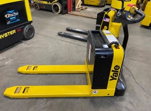
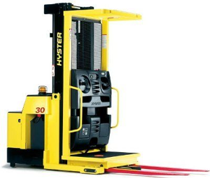
Hyster-Yale Pallet Truck MPB040-EN24T2236
Need answers fast?
Explore the manual using AI.
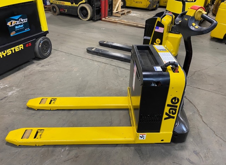
The Hyster-Yale Pallet Truck MPB040-EN24T2236 is a robust and efficient electric pallet truck designed for heavy-duty material handling. Known for its reliability and ease of use, this model enhances productivity in warehouse and distribution environments. Regular maintenance ensures optimal performance and longevity of the equipment.
Turn manuals into instant answers
with your AI-powered assistantTurn manuals into instant answers
with your AI-powered assistant
Manual for Hyster-Yale Pallet Truck MPB040-EN24T2236
Complete asset maintenance, one click away
Get instant access to all the maintenance information you need. Empower technicians to perform preventive maintenance with asset packages, ready to use right out of the box.

Documents & Manuals
Find all the essential guides in one place.
 Tensioning Guide
- Belt-diagram
- C-120 pulleys
+ 13 more

Work Order Templates
Pre-built workflows to keep your asset running smoothly.
- Daily Electrical System Inspection
- Replace Roller and Pulley
- Install Engine B-120
+ 29 more

Procedures
Integrate maintenance plans directly into your work orders.
- Motion Industries
- Applied Industrial Technologies
- Electrical Brothers
+ 5 more

Parts
Access the parts list for your equipment in MaintainX.
- Drive Motor
- B2 Rollers
- Tensioning System
+ 40 more
Hyster-Yale Pallet Truck MPB040-EN24T2236
Create an account to install this asset package.
Maintenance Plans for Hyster-Yale Pallet Truck Model MPB040-EN24T2236
Integrate maintenance plans directly into your work orders in MaintainX.
Hydraulic Pump Replacement
REMOVE:
1. Remove the hydraulic unit from the lift truck. Refer to the Hydraulic Unit in this section.
2. Clean the reservoir and pump area to prevent contaminants from entering the hydraulic system.
3. Remove the capscrews retaining the reservoir to the hydraulic unit. Tap around the perimeter to break the seal and separate the reservoir from the motor assembly.
4. Remove the spring retaining screw from the suction tube.
5. Remove the suction tube and strainer by pulling down and out.
6. Remove the four capscrews retaining the pump to the drive motor.
7. Disassemble the pump assembly and coupling from the adapter.
INSTALL:

Hydraulic Cylinder Replacement
WARNING: Put blocks under each fork. Position blocks on both sides of the drive wheel. The blocks must prevent the lift truck from falling and causing personal injury or damage.
WARNING: Be careful when removing or installing snap rings. The snap rings can come loose during removal or installation with enough force to cause a personal injury. Always use the correct snap ring pliers, and wear eye and face protection during removal and installation.
Raise the motorized lift truck forks/platform to one half its maximum height.
Place blocks under the forks. Block the drive wheel.
Remove the drive unit compartment cover.
Separate the frames.
Manually collapse the piston into the cylinder while depressing the lower switch.
Relieve pressure from the hydraulic cylinder.
Drive the roll pin retaining the top clevis pin out of the frame and clevis pin. Remove the top clevis pin.
Hydraulic Unit Replacement
WARNING: Batteries are heavy and can cause personal injury. Use care to avoid injury. DO NOT put hands, arms, feet, and/or legs between the battery and a solid object.
WARNING: Put blocks under each side of the truck under the drive unit frame. Position blocks on both sides of the load wheels. The blocks must prevent the lift truck from falling and causing personal injury or property damage.
WARNING: The capacitor in the transistor controller can hold an electrical charge after the battery is disconnected. To prevent electrical shock and personal injury, discharge the capacitor before inspecting or repairing any component in the drive unit compartment. Wear safety glasses. Make certain the battery has been disconnected.
CAUTION: Make certain the hydraulic cylinder is fully collapsed.
Remove the drive unit compartment cover.
Disconnect the battery. Use a spreader bar and lifting device to remove the battery. DO NOT allow the battery move from side to side. Make sure the battery cables have clearance.
Raise the drive wheel off the floor and put blocks under both sides of the drive unit frame.
Drain the hydraulic oil from the hydraulic unit into an appropriate container.
Tag and disconnect all of the electrical wires from the hydraulic unit.
Hydraulic Pump Reservoir Replacement
REMOVE:
The reservoir of the hydraulic pump unit can be removed without removing the complete hydraulic unit.
The motor will also come loose, with one set of screws holding the reservoir to the subunit to the motor.
WARNING: The capacitor in the transistor controller can hold an electrical charge after the battery is disconnected. To prevent electrical shock and personal injury, discharge the capacitor before inspecting or repairing any component in the drive unit compartment. Wear safety glasses. Make certain the battery has been disconnected. Refer to the section Steering Mechanism 1600 YRM 1004.
CAUTION: Make certain the hydraulic cylinder is fully collapsed.
NOTE: The reservoir must be lowered below the suction tube before attempting to move the reservoir away from the lift truck. Remember the reservoir may contain hydraulic oil. Dispose of all used oil in accordance with local regulations.
1. Move the key to the OFF position. Disconnect the battery.
2. Remove the drive unit compartment cover.
3. Discharge the capacitor in the transistor controller.
Relief Valve Adjustment
WARNING: DO NOT make repairs or adjustments unless you have been properly trained and authorized to do so.
Always wear the proper protective equipment including eye protection and petroleum resistant gloves when servicing hydraulic components.
Completely lower all lift components and relieve pressure before disassembling any part of the lift pump or disconnecting any hydraulic hoses.
The hydraulic oil is hot at normal operating temperatures. Be careful when draining the oil.
Never put your hands on pressurized hydraulic components. Pressurized hydraulic oil escaping through pin-hole leaks can be injected into the skin.
CAUTION: DO NOT OVERFILL. Oil will leak from the breather/ filler cap if too full.
NOTE: Check the hydraulic oil level in the reservoir when oil is at room temperature.
Hydraulic oil temperature
Forks completely lowered to relieve pressure from hydraulic circuit?
Parts for Hyster-Yale Pallet Truck MPB040-EN24T2236
Access the parts list for your equipment in MaintainX.
Contactor, F/R To S/N A827N13548U
YL 505175504
Pivoting Battery Tray
YL 518739600
Battery Disconnect Handle, W/Screws And Nuts
YL 503954200
Drive Wheel Hub
YL 501087300
Woodruff Key
YL 016247100
Contactor, F/R To S/N A827N13548U
YL 505175504
Pivoting Battery Tray
YL 518739600
Battery Disconnect Handle, W/Screws And Nuts
YL 503954200
Drive Wheel Hub
YL 501087300
Woodruff Key
YL 016247100
Contactor, F/R To S/N A827N13548U
YL 505175504
Pivoting Battery Tray
YL 518739600
Battery Disconnect Handle, W/Screws And Nuts
YL 503954200
Drive Wheel Hub
YL 501087300
Woodruff Key
YL 016247100
Unlock efficiency
with MaintainX CoPilot
MaintainX CoPilot is your expert colleague, on call 24/7, helping your team find the answers they need to keep equipment running.
Reduce Unplanned Downtime
Ensure your team follows consistent procedures to minimize equipment failures and costly delays.
Maximize Asset Availability
Keep your assets running longer and more reliably, with standardized maintenance workflows from OEM manuals.
Lower Maintenance Costs
Turn any technician into an expert to streamline operations, maintain more assets, and reduce overall costs.
Thousands of companies manage their assets with MaintainX

'%3e%3cpath%20fill='url(%23b)'%20d='M66.008%2080.068c-5.084-.786-9.763-3.834-12.442-8.68a16.942%2016.942%200%200%201-1.87-5.18c1.096.19%202.203.476%203.298.87%206.525%202.333%2010.836%207.68%2011.014%2012.99ZM51.47%2061.576c.488-5.524%203.62-10.716%208.847-13.597a17.132%2017.132%200%200%201%2011.335-1.882c-.798%208.145-7.43%2014.848-16.038%2015.599-1.417.119-2.799.07-4.144-.12Zm28.564-11.478a17.513%2017.513%200%200%201%203.727%204.62c4.608%208.335%201.584%2018.813-6.75%2023.409a16.988%2016.988%200%200%201-4.359%201.679%2019.624%2019.624%200%200%201-3.977-12.776c.346-7.561%204.942-13.931%2011.36-16.932Z'/%3e%3cpath%20fill='%23110F0D'%20fill-rule='evenodd'%20d='M142.831%2048.324h4.977V77.03h-4.977V48.324Zm27.278%2013.002c.322%201.048.453%202.263.453%203.62v12.073h-4.787V66.208c0-.75-.047-1.572-.154-2.143-.453-2.382-1.822-3.572-4.215-3.572-2.31%200-3.882%201.274-4.43%203.476-.143.596-.226%201.405-.226%202.25v10.8h-4.787V56.623h4.477v2.989c1.536-2.5%203.906-3.43%206.371-3.43%203.488%200%206.263%201.68%207.298%205.144Zm24.636%207.323c0%203.882-2.358%206.525-5.763%207.727-1.298.453-2.632.643-4.62.643h-10.169V48.324h9.085c1.691%200%203.156.143%204.049.38%203.465.93%205.727%203.68%205.727%207.335%200%202.441-.81%204.156-2.762%205.644%202.905%201.417%204.453%203.727%204.453%206.966Zm-15.634-8.656h4.584c1.024%200%201.917-.143%202.536-.417%201.215-.548%201.905-1.608%201.905-3.167%200-1.548-.643-2.572-1.845-3.132-.691-.31-1.762-.452-2.763-.452h-4.417v7.168Zm10.716%208.465c0-1.536-.893-3.37-3.227-3.893-.428-.095-1.036-.143-1.571-.143h-5.918v8.085h5.501c.56%200%201.429-.048%201.953-.167%201.94-.453%203.262-1.846%203.262-3.882Zm47.747-11.847-8.097%2020.408h-4.429l-8.109-20.408h5.191l5.192%2014.574%205.108-14.574h5.144Zm-20.218%2010.002c0%20.69-.036%201.262-.155%201.94h-15.943c.631%202.87%202.714%204.728%205.882%204.728%202.131%200%203.607-.882%204.703-2.525h4.87c-1.762%204.144-5.204%206.692-9.657%206.692-6.084%200-10.537-4.858-10.537-10.49%200-6.108%204.524-10.776%2010.335-10.776%206.239%200%2010.442%204.954%2010.502%2010.43Zm-4.763-1.405c-.333-2.846-2.643-4.858-5.691-4.858-2.894%200-5.287%201.929-5.621%204.858h11.312Zm-72.667%203.44c0%204.787-3.287%208.371-9.419%208.371H119.363V64.66c-1.917.274-3.87.69-5.811%201.238l4.537%2011.121h-5.418l-3.596-9.585c-5.144%202.084-10.085%205.216-14.217%209.585h-4.786L101.8%2048.312h4.56l5.68%2013.883a44.112%2044.112%200%200%201%207.323-1.774V48.312h9.084c1.703%200%203.156.143%204.061.393%203.453.929%205.727%203.667%205.727%207.323%200%201.917-.738%204.179-2.81%205.691%203.06%201.56%204.501%204.025%204.501%206.93Zm-15.634-8.667a62.664%2062.664%200%200%201%202.06-.036c1.703.012%203.239.131%204.608.37%201.441-.549%202.357-1.727%202.357-3.537%200-1.941-.881-3.144-2.488-3.667-.548-.18-1.358-.286-2.322-.286h-4.215v7.156Zm-16.55%203.905-3.715-9.894-6.394%2016.502c2.833-2.595%206.263-4.858%2010.109-6.608Zm27.254%204.74c0-2.775-3.131-4.347-8.513-4.418-.715%200-1.441.011-2.191.047v8.252h5.918c2.548%200%204.786-1.37%204.786-3.882Z'%20clip-rule='evenodd'/%3e%3c/g%3e%3cdefs%3e%3clinearGradient%20id='b'%20x1='51.47'%20x2='85.916'%20y1='62.946'%20y2='62.946'%20gradientUnits='userSpaceOnUse'%3e%3cstop%20stop-color='%23CD9F28'/%3e%3cstop%20offset='1'%20stop-color='%23ECD80B'/%3e%3c/linearGradient%3e%3cclipPath%20id='a'%3e%3cpath%20fill='%23fff'%20d='M51.47%2045.728h186.104V80.14H51.47z'/%3e%3c/clipPath%3e%3c/defs%3e%3c/svg%3e)


More from Hyster-Yale


Explore Other Assets


© 2026 MaintainX. All rights reserved.