


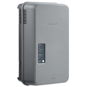
Honeywell Gas Detector GasAlert MaxXT2
Need answers fast?
Explore the manual using AI.
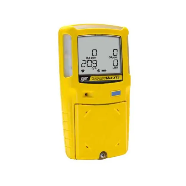
The Honeywell Gas Detector GasAlert MaxXT2 is a reliable and advanced gas detection device designed for industrial safety. This portable model ensures accurate monitoring of hazardous gases, providing essential protection in various environments. With its robust features and user-friendly interface, it is an ideal choice for professionals seeking effective gas detection solutions.
Turn manuals into instant answers
with your AI-powered assistantTurn manuals into instant answers
with your AI-powered assistant
Manual for Honeywell Gas Detector GasAlert MaxXT2
Complete asset maintenance, one click away
Get instant access to all the maintenance information you need. Empower technicians to perform preventive maintenance with asset packages, ready to use right out of the box.

Documents & Manuals
Find all the essential guides in one place.
 Tensioning Guide
- Belt-diagram
- C-120 pulleys
+ 13 more

Work Order Templates
Pre-built workflows to keep your asset running smoothly.
- Daily Electrical System Inspection
- Replace Roller and Pulley
- Install Engine B-120
+ 29 more

Procedures
Integrate maintenance plans directly into your work orders.
- Motion Industries
- Applied Industrial Technologies
- Electrical Brothers
+ 5 more

Parts
Access the parts list for your equipment in MaintainX.
- Drive Motor
- B2 Rollers
- Tensioning System
+ 40 more
Honeywell Gas Detector GasAlert MaxXT2
Create an account to install this asset package.
Maintenance Plans for Honeywell Gas Detector Model GasAlert MaxXT2
Integrate maintenance plans directly into your work orders in MaintainX.
Pump Filters Replacement
Warning: Ensure the pump is turned off before starting the procedure.
Is the pump turned off?
Remove the one machine screw from the pump inlet and gently lift the bottom of the inlet outward at a 45° angle.
Was the pump inlet removed successfully?
Gently lift the pump inlet upwards to remove. Ensure the hook on the pump inlet clears the housing. The particulate filter is located inside the pump inlet and the moisture filter is located on the rear shell.
Were the filters located successfully?
Choose the type of filter to replace
Reattach the pump inlet and replace the screw. Tighten the screw using 3-4 in-lbs. torque. Do not overtighten.
Was the pump inlet reattached successfully?

Sensor or Sensor Filter Replacement
WARNING! To avoid personal injury and/or property damage, use only sensors that are specifically designed for the detector.
Each sensor has a high degree of resistance to common vapors and gases. To clear a sensor, move the detector to a clean environment and wait 10 to 30 minutes.
Do not expose a sensor to vapors from inorganic solvents such as fumes from paint thinners, or organic solvents such as benzoic acids and acrylic acids).
Deactivate the detector.
Remove the pump inlet screw and the pump inlet.
Remove the six machine screws from the rear shell.
Carefully remove the rear shell by lifting upward and tilting to the left. The front and rear shells are laying flat side by side.
Remove the two PCB screws.
Lift the PCB upward and tilt to the left. Lay the PCB (sensors facing up) onto the rear shell.
Battery Charging
WARNING! The detector must be charged in a safe area that is free of hazardous gas in temperatures of 32°F to 113°F (0°C to 45°C).
Deactivate the detector
Plug the charger into a AC outlet
CAUTION! The charging adapter is voltage specific to your region. Use of the charging adapter outside your region will damage the charger and the detector.
Attach the charging adapter to the charger interface
Enter the charging time in hours
Charging indicator stops flashing and displays to indicate a full charge
Remove the adapter and activate the detector
NOTE! To preserve the life of the battery, deactivate the detector when not in use. The detector may be warm immediately after charging. This is normal.
Parts for Honeywell Gas Detector GasAlert MaxXT2
Access the parts list for your equipment in MaintainX.
Combustible Sensor
SR-WMC75C
Hydrophobic Filters
XT-RF-H50
Carrying Holster
GA-HXT
Docking Module
DOCK2-0-1C1M-00-N
Charging Adapter
GA-PA-1
Combustible Sensor
SR-WMC75C
Hydrophobic Filters
XT-RF-H50
Carrying Holster
GA-HXT
Docking Module
DOCK2-0-1C1M-00-N
Charging Adapter
GA-PA-1
Combustible Sensor
SR-WMC75C
Hydrophobic Filters
XT-RF-H50
Carrying Holster
GA-HXT
Docking Module
DOCK2-0-1C1M-00-N
Charging Adapter
GA-PA-1
Unlock efficiency
with MaintainX CoPilot
MaintainX CoPilot is your expert colleague, on call 24/7, helping your team find the answers they need to keep equipment running.
Reduce Unplanned Downtime
Ensure your team follows consistent procedures to minimize equipment failures and costly delays.
Maximize Asset Availability
Keep your assets running longer and more reliably, with standardized maintenance workflows from OEM manuals.
Lower Maintenance Costs
Turn any technician into an expert to streamline operations, maintain more assets, and reduce overall costs.
Thousands of companies manage their assets with MaintainX

'%3e%3cpath%20fill='url(%23b)'%20d='M66.008%2080.068c-5.084-.786-9.763-3.834-12.442-8.68a16.942%2016.942%200%200%201-1.87-5.18c1.096.19%202.203.476%203.298.87%206.525%202.333%2010.836%207.68%2011.014%2012.99ZM51.47%2061.576c.488-5.524%203.62-10.716%208.847-13.597a17.132%2017.132%200%200%201%2011.335-1.882c-.798%208.145-7.43%2014.848-16.038%2015.599-1.417.119-2.799.07-4.144-.12Zm28.564-11.478a17.513%2017.513%200%200%201%203.727%204.62c4.608%208.335%201.584%2018.813-6.75%2023.409a16.988%2016.988%200%200%201-4.359%201.679%2019.624%2019.624%200%200%201-3.977-12.776c.346-7.561%204.942-13.931%2011.36-16.932Z'/%3e%3cpath%20fill='%23110F0D'%20fill-rule='evenodd'%20d='M142.831%2048.324h4.977V77.03h-4.977V48.324Zm27.278%2013.002c.322%201.048.453%202.263.453%203.62v12.073h-4.787V66.208c0-.75-.047-1.572-.154-2.143-.453-2.382-1.822-3.572-4.215-3.572-2.31%200-3.882%201.274-4.43%203.476-.143.596-.226%201.405-.226%202.25v10.8h-4.787V56.623h4.477v2.989c1.536-2.5%203.906-3.43%206.371-3.43%203.488%200%206.263%201.68%207.298%205.144Zm24.636%207.323c0%203.882-2.358%206.525-5.763%207.727-1.298.453-2.632.643-4.62.643h-10.169V48.324h9.085c1.691%200%203.156.143%204.049.38%203.465.93%205.727%203.68%205.727%207.335%200%202.441-.81%204.156-2.762%205.644%202.905%201.417%204.453%203.727%204.453%206.966Zm-15.634-8.656h4.584c1.024%200%201.917-.143%202.536-.417%201.215-.548%201.905-1.608%201.905-3.167%200-1.548-.643-2.572-1.845-3.132-.691-.31-1.762-.452-2.763-.452h-4.417v7.168Zm10.716%208.465c0-1.536-.893-3.37-3.227-3.893-.428-.095-1.036-.143-1.571-.143h-5.918v8.085h5.501c.56%200%201.429-.048%201.953-.167%201.94-.453%203.262-1.846%203.262-3.882Zm47.747-11.847-8.097%2020.408h-4.429l-8.109-20.408h5.191l5.192%2014.574%205.108-14.574h5.144Zm-20.218%2010.002c0%20.69-.036%201.262-.155%201.94h-15.943c.631%202.87%202.714%204.728%205.882%204.728%202.131%200%203.607-.882%204.703-2.525h4.87c-1.762%204.144-5.204%206.692-9.657%206.692-6.084%200-10.537-4.858-10.537-10.49%200-6.108%204.524-10.776%2010.335-10.776%206.239%200%2010.442%204.954%2010.502%2010.43Zm-4.763-1.405c-.333-2.846-2.643-4.858-5.691-4.858-2.894%200-5.287%201.929-5.621%204.858h11.312Zm-72.667%203.44c0%204.787-3.287%208.371-9.419%208.371H119.363V64.66c-1.917.274-3.87.69-5.811%201.238l4.537%2011.121h-5.418l-3.596-9.585c-5.144%202.084-10.085%205.216-14.217%209.585h-4.786L101.8%2048.312h4.56l5.68%2013.883a44.112%2044.112%200%200%201%207.323-1.774V48.312h9.084c1.703%200%203.156.143%204.061.393%203.453.929%205.727%203.667%205.727%207.323%200%201.917-.738%204.179-2.81%205.691%203.06%201.56%204.501%204.025%204.501%206.93Zm-15.634-8.667a62.664%2062.664%200%200%201%202.06-.036c1.703.012%203.239.131%204.608.37%201.441-.549%202.357-1.727%202.357-3.537%200-1.941-.881-3.144-2.488-3.667-.548-.18-1.358-.286-2.322-.286h-4.215v7.156Zm-16.55%203.905-3.715-9.894-6.394%2016.502c2.833-2.595%206.263-4.858%2010.109-6.608Zm27.254%204.74c0-2.775-3.131-4.347-8.513-4.418-.715%200-1.441.011-2.191.047v8.252h5.918c2.548%200%204.786-1.37%204.786-3.882Z'%20clip-rule='evenodd'/%3e%3c/g%3e%3cdefs%3e%3clinearGradient%20id='b'%20x1='51.47'%20x2='85.916'%20y1='62.946'%20y2='62.946'%20gradientUnits='userSpaceOnUse'%3e%3cstop%20stop-color='%23CD9F28'/%3e%3cstop%20offset='1'%20stop-color='%23ECD80B'/%3e%3c/linearGradient%3e%3cclipPath%20id='a'%3e%3cpath%20fill='%23fff'%20d='M51.47%2045.728h186.104V80.14H51.47z'/%3e%3c/clipPath%3e%3c/defs%3e%3c/svg%3e)


More from Honeywell


Explore Other Assets


© 2026 MaintainX. All rights reserved.