


Hobart Hobart - Handler 210 MVP Handler 210 MVP
Need answers fast?
Explore the manual using AI.
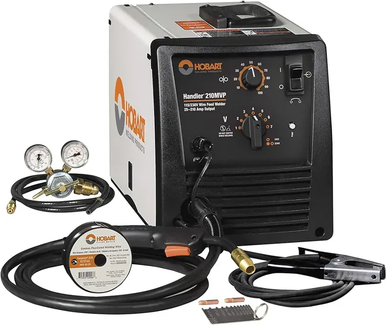
The Hobart Handler 210 MVP is a versatile MIG welding machine designed for both professionals and hobbyists. Known for its reliability and ease of use, this model offers exceptional performance in various welding applications, making it an ideal choice for metal fabrication and repair tasks.
Turn manuals into instant answers
with your AI-powered assistantTurn manuals into instant answers
with your AI-powered assistant
Manual for Hobart Hobart - Handler 210 MVP Handler 210 MVP
Complete asset maintenance, one click away
Get instant access to all the maintenance information you need. Empower technicians to perform preventive maintenance with asset packages, ready to use right out of the box.

Documents & Manuals
Find all the essential guides in one place.
 Tensioning Guide
- Belt-diagram
- C-120 pulleys
+ 13 more

Work Order Templates
Pre-built workflows to keep your asset running smoothly.
- Daily Electrical System Inspection
- Replace Roller and Pulley
- Install Engine B-120
+ 29 more

Procedures
Integrate maintenance plans directly into your work orders.
- Motion Industries
- Applied Industrial Technologies
- Electrical Brothers
+ 5 more

Parts
Access the parts list for your equipment in MaintainX.
- Drive Motor
- B2 Rollers
- Tensioning System
+ 40 more
Hobart Hobart - Handler 210 MVP Handler 210 MVP
Create an account to install this asset package.
Maintenance Plans for Hobart Hobart - Handler 210 MVP Model Handler 210 MVP
Integrate maintenance plans directly into your work orders in MaintainX.
6 Months Check
- Clean drive rolls.
- Clean inside unit.;

Replacing Switch And/Or Head Tube
Turn Off welding power source /wire feeder and disconnect gun
1. Remove screws and nuts
2. Remove handle halves
3. Remove switch housing. Install new switch and connect leads (polarity is not important). Reassemble in reverse order. If replacing head tube, continue to end of figure
4. Secure head tube in vice.
5. Loosen jam nut. Remove from vice and turn head tube out by hand.
6. Hand-tighten head tube into cable connector
7. Place head tube in vice and tighten until nuts are tight
8. Remove from vice. Reposition handle halves, and install switch housing
Changing Drive Roll Or Wire Inlet Guide
1 Inlet Wire Guide Securing Screw
2 Inlet Wire Guide
Loosen thumbscrew. Slide tip as close to drive rolls as possible without touching. Tighten thumbscrew
3 Drive Roll
The drive roll consists of two different grooves. The stamped markings on the end surface of the drive roll refers to the groove on the opposite side of the drive roll. The groove closest to the motor shaft is the proper groove to thread (see Section 5-16). VK (Knurled) groove is used for flux cored wire and V groove is used for solid wire
4 Retaining Pin
To secure drive roll, locate open slot and push drive roll completely over retaining pin, then rotate drive roll (1/4 turn) to closed slot.
5 Drive Roll Tension Knob
Using flux core wire with VK groove, tension should be set between 1-1/2 to 2. Higher setting may cause welding wire to deform and not allow proper feeding. Flux Core Wire − Recommended stickout is 1/2 in. (12.7 mm) from gun tip. Solid Wire − Recommended stickout is 3/8 in. (9.5 mm) from gun tip;
3 Months Check
- Replace unreadable labels
- Clean weld terminals.
- Replace damaged gas hose.
- Check and replace weld cables if necessary.
- Check and replace cords if necessary.
- Check and replace gun cables if necessary.;
Changing Nozzle, Contact Tip, Adapter And Liner, And Cleaning Gun Casing
1. Remove nozzle, contact tip, and adapter.
2. Cut off wire and disconnect gun from feeder
3. Unscrew and remove liner
4. Lay gun cable out straight before installing new liner
5. Blow out gun casing
6. Install Liner
7. Reassemble gun in reverse order from taking it apart;
Parts for Hobart Hobart - Handler 210 MVP Handler 210 MVP
Access the parts list for your equipment in MaintainX.
Replacement Liners
196 140
Gasless Flux Cored Nozzle
770 487
Contact Tips
770 174
Replacement Drive Rolls
246 565
MIG Nozzle (Standard)
770 404
Replacement Liners
196 140
Gasless Flux Cored Nozzle
770 487
Contact Tips
770 174
Replacement Drive Rolls
246 565
MIG Nozzle (Standard)
770 404
Replacement Liners
196 140
Gasless Flux Cored Nozzle
770 487
Contact Tips
770 174
Replacement Drive Rolls
246 565
MIG Nozzle (Standard)
770 404
Unlock efficiency
with MaintainX CoPilot
MaintainX CoPilot is your expert colleague, on call 24/7, helping your team find the answers they need to keep equipment running.
Reduce Unplanned Downtime
Ensure your team follows consistent procedures to minimize equipment failures and costly delays.
Maximize Asset Availability
Keep your assets running longer and more reliably, with standardized maintenance workflows from OEM manuals.
Lower Maintenance Costs
Turn any technician into an expert to streamline operations, maintain more assets, and reduce overall costs.
Thousands of companies manage their assets with MaintainX

'%3e%3cpath%20fill='url(%23b)'%20d='M66.008%2080.068c-5.084-.786-9.763-3.834-12.442-8.68a16.942%2016.942%200%200%201-1.87-5.18c1.096.19%202.203.476%203.298.87%206.525%202.333%2010.836%207.68%2011.014%2012.99ZM51.47%2061.576c.488-5.524%203.62-10.716%208.847-13.597a17.132%2017.132%200%200%201%2011.335-1.882c-.798%208.145-7.43%2014.848-16.038%2015.599-1.417.119-2.799.07-4.144-.12Zm28.564-11.478a17.513%2017.513%200%200%201%203.727%204.62c4.608%208.335%201.584%2018.813-6.75%2023.409a16.988%2016.988%200%200%201-4.359%201.679%2019.624%2019.624%200%200%201-3.977-12.776c.346-7.561%204.942-13.931%2011.36-16.932Z'/%3e%3cpath%20fill='%23110F0D'%20fill-rule='evenodd'%20d='M142.831%2048.324h4.977V77.03h-4.977V48.324Zm27.278%2013.002c.322%201.048.453%202.263.453%203.62v12.073h-4.787V66.208c0-.75-.047-1.572-.154-2.143-.453-2.382-1.822-3.572-4.215-3.572-2.31%200-3.882%201.274-4.43%203.476-.143.596-.226%201.405-.226%202.25v10.8h-4.787V56.623h4.477v2.989c1.536-2.5%203.906-3.43%206.371-3.43%203.488%200%206.263%201.68%207.298%205.144Zm24.636%207.323c0%203.882-2.358%206.525-5.763%207.727-1.298.453-2.632.643-4.62.643h-10.169V48.324h9.085c1.691%200%203.156.143%204.049.38%203.465.93%205.727%203.68%205.727%207.335%200%202.441-.81%204.156-2.762%205.644%202.905%201.417%204.453%203.727%204.453%206.966Zm-15.634-8.656h4.584c1.024%200%201.917-.143%202.536-.417%201.215-.548%201.905-1.608%201.905-3.167%200-1.548-.643-2.572-1.845-3.132-.691-.31-1.762-.452-2.763-.452h-4.417v7.168Zm10.716%208.465c0-1.536-.893-3.37-3.227-3.893-.428-.095-1.036-.143-1.571-.143h-5.918v8.085h5.501c.56%200%201.429-.048%201.953-.167%201.94-.453%203.262-1.846%203.262-3.882Zm47.747-11.847-8.097%2020.408h-4.429l-8.109-20.408h5.191l5.192%2014.574%205.108-14.574h5.144Zm-20.218%2010.002c0%20.69-.036%201.262-.155%201.94h-15.943c.631%202.87%202.714%204.728%205.882%204.728%202.131%200%203.607-.882%204.703-2.525h4.87c-1.762%204.144-5.204%206.692-9.657%206.692-6.084%200-10.537-4.858-10.537-10.49%200-6.108%204.524-10.776%2010.335-10.776%206.239%200%2010.442%204.954%2010.502%2010.43Zm-4.763-1.405c-.333-2.846-2.643-4.858-5.691-4.858-2.894%200-5.287%201.929-5.621%204.858h11.312Zm-72.667%203.44c0%204.787-3.287%208.371-9.419%208.371H119.363V64.66c-1.917.274-3.87.69-5.811%201.238l4.537%2011.121h-5.418l-3.596-9.585c-5.144%202.084-10.085%205.216-14.217%209.585h-4.786L101.8%2048.312h4.56l5.68%2013.883a44.112%2044.112%200%200%201%207.323-1.774V48.312h9.084c1.703%200%203.156.143%204.061.393%203.453.929%205.727%203.667%205.727%207.323%200%201.917-.738%204.179-2.81%205.691%203.06%201.56%204.501%204.025%204.501%206.93Zm-15.634-8.667a62.664%2062.664%200%200%201%202.06-.036c1.703.012%203.239.131%204.608.37%201.441-.549%202.357-1.727%202.357-3.537%200-1.941-.881-3.144-2.488-3.667-.548-.18-1.358-.286-2.322-.286h-4.215v7.156Zm-16.55%203.905-3.715-9.894-6.394%2016.502c2.833-2.595%206.263-4.858%2010.109-6.608Zm27.254%204.74c0-2.775-3.131-4.347-8.513-4.418-.715%200-1.441.011-2.191.047v8.252h5.918c2.548%200%204.786-1.37%204.786-3.882Z'%20clip-rule='evenodd'/%3e%3c/g%3e%3cdefs%3e%3clinearGradient%20id='b'%20x1='51.47'%20x2='85.916'%20y1='62.946'%20y2='62.946'%20gradientUnits='userSpaceOnUse'%3e%3cstop%20stop-color='%23CD9F28'/%3e%3cstop%20offset='1'%20stop-color='%23ECD80B'/%3e%3c/linearGradient%3e%3cclipPath%20id='a'%3e%3cpath%20fill='%23fff'%20d='M51.47%2045.728h186.104V80.14H51.47z'/%3e%3c/clipPath%3e%3c/defs%3e%3c/svg%3e)


More from Hobart


Explore Other Assets


© 2026 MaintainX. All rights reserved.