


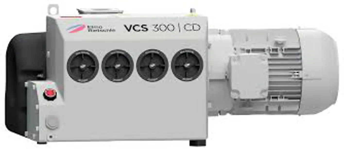
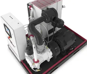
Gardner Denver Vacuum Pump VCX 200
Need answers fast?
Explore the manual using AI.
Turn manuals into instant answers
with your AI-powered assistantTurn manuals into instant answers
with your AI-powered assistant
Manual for Gardner Denver Vacuum Pump VCX 200
Complete asset maintenance, one click away
Get instant access to all the maintenance information you need. Empower technicians to perform preventive maintenance with asset packages, ready to use right out of the box.

Documents & Manuals
Find all the essential guides in one place.
 Tensioning Guide
- Belt-diagram
- C-120 pulleys
+ 13 more

Work Order Templates
Pre-built workflows to keep your asset running smoothly.
- Daily Electrical System Inspection
- Replace Roller and Pulley
- Install Engine B-120
+ 29 more

Procedures
Integrate maintenance plans directly into your work orders.
- Motion Industries
- Applied Industrial Technologies
- Electrical Brothers
+ 5 more

Parts
Access the parts list for your equipment in MaintainX.
- Drive Motor
- B2 Rollers
- Tensioning System
+ 40 more
Gardner Denver Vacuum Pump VCX 200
Create an account to install this asset package.
Maintenance Plans for Gardner Denver Vacuum Pump Model VCX 200
Integrate maintenance plans directly into your work orders in MaintainX.
1 Monthly Vacuum Pump Maintenance
Check the pipes and screws for leaks and ensure their tight fit and if necessary re-seal or re-tighten.
Check the terminal box and cable inlet holes for leaks and if necessary re-seal.
Clean the ventilation slots on the machine and the motor cooling ribs.
Cleaning the oil cooler.
CAUTION: Danger of injury when dealing with compressed air! When the cooler is blown off with compressed air, loose solid particles or powder dust swirling around may cause injury to the eyes. Inhaling can damage lungs. Wear protective glasses and dust mask when cleaning the cooler with compressed air.
NOTICE: Property damage due to insufficient maintenance of the oil cooler! Due to soiled cooling ribs of the oil cooler (e.g. From dust) and insufficient maintenance, the cooling capacity of the machine is reduced. This can cause damage of the machine.
Clean the oil cooler at regular intervals.
Switch the machine off, secure it against accidental switching on and vent to atmospheric pressure. Let the pump cool down.
Release a screw (Fig. 9/s2) and two nuts (Fig. 9/n2) on the hood.

1 Yearly Vacuum Pump Maintenance
NOTICE: Property damage due to defective coupling sleeve! Defective sleeves can cause breaking of the rotor shaft and blackout failure of the machine.
NOTICE Property damage due to frequent starting and high ambient temperature! Frequent starting and high ambient temperature reduces the lifetime of the sleeve.
Regularly check the coupling sleeve for wear.
Switch off the motor and ensure that it cannot be switched on again.
Tighten the eyebolt on the motor firmly.
Secure the lifting gear on the ring bolt of the motor.
Undo the screws on the motor flange.
Remove the motor axially with the coupling half on the motor side from the motor flange and suspend with the lifting gear.
Check the sleeve for damage and replace if necessary.
Vacuum Pump Cleaning
The vacuum pump must regularly be checked for dust deposits and cleaned, if necessary. The cleaning interval depends on the operational requirements.
a) Clean the vacuum pump with a dump cloth or using a vacuum cleaner. Remove dust deposits:
• Between the cooling ribs of the motor
• On the hood
• Oil remover housing
Cleaning can also take place in connection with the cleaning of the oil cooler. See chapter 7.8.
2000 Hourly/1 Yearly Hourly Vacuum Pump Maintenance
NOTICE: Property damage due to insufficient maintenance! If the air oil removal devices are strongly polluted, their functioning will be reduced, which can cause machine failures.
Check de-oiling elements for soiling at regular intervals.
Enter the filter resistance. Replace de-oiling elements if the filter resistance exceeds 700 mbar.
Do not clean the de-oiling elements. Always replace the de-oiling elements by new ones.
NOTE: For monitoring the level of soiling of the de-oiling elements, we recommend using a pressure gauge (ZDM). This enables a check of the filter resistance with temporary atmospheric suction.
The air oil removal devices (4x) may be contaminated with particles of dirt when the machine has been running for a long time (power consumption and pump temperature increase). Reduce the change intervals accordingly depending on how contaminated the discharged medium is.
Switch the machine off, secure it against accidental switching on and vent to atmospheric pressure. Let the pump cool down.
Unscrew air oil removal elements with a ring spanner (width across flats 19 mm) counter-clockwise.
Push in the new air oil removal elements and screw in clockwise. Tightening torque: max. 15 Nm Thee air oil removal elements shall be flush with the oil remover housing.
500 Hourly Vacuum Pump Maintenance
Oil Change Procedure
Switch off the machine and secure it against accidental switching on
Vent the pump to atmospheric pressure and let it cool down
Open the catch of the oil filling point (Fig. 7/H)
Open the oil discharge point (Fig. 7/K) and completely discharge the used oil
Close the oil discharge point (Fig. 7/K)
Fill in new oil through the oil filling point (Fig. 7/H)
Check the oil level in the sight glasses (Fig. 7/I)
Sign off on the oil change procedure
Unlock efficiency
with MaintainX CoPilot
MaintainX CoPilot is your expert colleague, on call 24/7, helping your team find the answers they need to keep equipment running.
Reduce Unplanned Downtime
Ensure your team follows consistent procedures to minimize equipment failures and costly delays.
Maximize Asset Availability
Keep your assets running longer and more reliably, with standardized maintenance workflows from OEM manuals.
Lower Maintenance Costs
Turn any technician into an expert to streamline operations, maintain more assets, and reduce overall costs.
Thousands of companies manage their assets with MaintainX

'%3e%3cpath%20fill='url(%23b)'%20d='M66.008%2080.068c-5.084-.786-9.763-3.834-12.442-8.68a16.942%2016.942%200%200%201-1.87-5.18c1.096.19%202.203.476%203.298.87%206.525%202.333%2010.836%207.68%2011.014%2012.99ZM51.47%2061.576c.488-5.524%203.62-10.716%208.847-13.597a17.132%2017.132%200%200%201%2011.335-1.882c-.798%208.145-7.43%2014.848-16.038%2015.599-1.417.119-2.799.07-4.144-.12Zm28.564-11.478a17.513%2017.513%200%200%201%203.727%204.62c4.608%208.335%201.584%2018.813-6.75%2023.409a16.988%2016.988%200%200%201-4.359%201.679%2019.624%2019.624%200%200%201-3.977-12.776c.346-7.561%204.942-13.931%2011.36-16.932Z'/%3e%3cpath%20fill='%23110F0D'%20fill-rule='evenodd'%20d='M142.831%2048.324h4.977V77.03h-4.977V48.324Zm27.278%2013.002c.322%201.048.453%202.263.453%203.62v12.073h-4.787V66.208c0-.75-.047-1.572-.154-2.143-.453-2.382-1.822-3.572-4.215-3.572-2.31%200-3.882%201.274-4.43%203.476-.143.596-.226%201.405-.226%202.25v10.8h-4.787V56.623h4.477v2.989c1.536-2.5%203.906-3.43%206.371-3.43%203.488%200%206.263%201.68%207.298%205.144Zm24.636%207.323c0%203.882-2.358%206.525-5.763%207.727-1.298.453-2.632.643-4.62.643h-10.169V48.324h9.085c1.691%200%203.156.143%204.049.38%203.465.93%205.727%203.68%205.727%207.335%200%202.441-.81%204.156-2.762%205.644%202.905%201.417%204.453%203.727%204.453%206.966Zm-15.634-8.656h4.584c1.024%200%201.917-.143%202.536-.417%201.215-.548%201.905-1.608%201.905-3.167%200-1.548-.643-2.572-1.845-3.132-.691-.31-1.762-.452-2.763-.452h-4.417v7.168Zm10.716%208.465c0-1.536-.893-3.37-3.227-3.893-.428-.095-1.036-.143-1.571-.143h-5.918v8.085h5.501c.56%200%201.429-.048%201.953-.167%201.94-.453%203.262-1.846%203.262-3.882Zm47.747-11.847-8.097%2020.408h-4.429l-8.109-20.408h5.191l5.192%2014.574%205.108-14.574h5.144Zm-20.218%2010.002c0%20.69-.036%201.262-.155%201.94h-15.943c.631%202.87%202.714%204.728%205.882%204.728%202.131%200%203.607-.882%204.703-2.525h4.87c-1.762%204.144-5.204%206.692-9.657%206.692-6.084%200-10.537-4.858-10.537-10.49%200-6.108%204.524-10.776%2010.335-10.776%206.239%200%2010.442%204.954%2010.502%2010.43Zm-4.763-1.405c-.333-2.846-2.643-4.858-5.691-4.858-2.894%200-5.287%201.929-5.621%204.858h11.312Zm-72.667%203.44c0%204.787-3.287%208.371-9.419%208.371H119.363V64.66c-1.917.274-3.87.69-5.811%201.238l4.537%2011.121h-5.418l-3.596-9.585c-5.144%202.084-10.085%205.216-14.217%209.585h-4.786L101.8%2048.312h4.56l5.68%2013.883a44.112%2044.112%200%200%201%207.323-1.774V48.312h9.084c1.703%200%203.156.143%204.061.393%203.453.929%205.727%203.667%205.727%207.323%200%201.917-.738%204.179-2.81%205.691%203.06%201.56%204.501%204.025%204.501%206.93Zm-15.634-8.667a62.664%2062.664%200%200%201%202.06-.036c1.703.012%203.239.131%204.608.37%201.441-.549%202.357-1.727%202.357-3.537%200-1.941-.881-3.144-2.488-3.667-.548-.18-1.358-.286-2.322-.286h-4.215v7.156Zm-16.55%203.905-3.715-9.894-6.394%2016.502c2.833-2.595%206.263-4.858%2010.109-6.608Zm27.254%204.74c0-2.775-3.131-4.347-8.513-4.418-.715%200-1.441.011-2.191.047v8.252h5.918c2.548%200%204.786-1.37%204.786-3.882Z'%20clip-rule='evenodd'/%3e%3c/g%3e%3cdefs%3e%3clinearGradient%20id='b'%20x1='51.47'%20x2='85.916'%20y1='62.946'%20y2='62.946'%20gradientUnits='userSpaceOnUse'%3e%3cstop%20stop-color='%23CD9F28'/%3e%3cstop%20offset='1'%20stop-color='%23ECD80B'/%3e%3c/linearGradient%3e%3cclipPath%20id='a'%3e%3cpath%20fill='%23fff'%20d='M51.47%2045.728h186.104V80.14H51.47z'/%3e%3c/clipPath%3e%3c/defs%3e%3c/svg%3e)


More from Gardner Denver
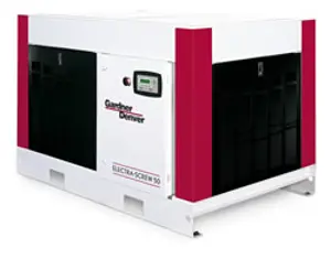


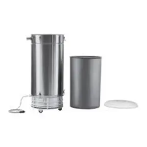


Explore Other Assets


© 2026 MaintainX. All rights reserved.