


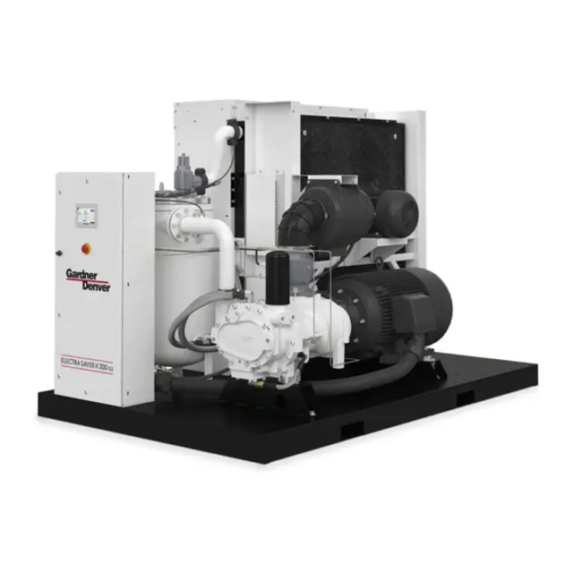
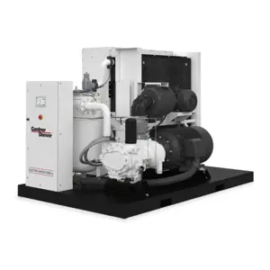
Gardner Denver Screw Air Compressor EBEQEJ
Need answers fast?
Explore the manual using AI.
Turn manuals into instant answers
with your AI-powered assistantTurn manuals into instant answers
with your AI-powered assistant
Manual for Gardner Denver Screw Air Compressor EBEQEJ
Complete asset maintenance, one click away
Get instant access to all the maintenance information you need. Empower technicians to perform preventive maintenance with asset packages, ready to use right out of the box.

Documents & Manuals
Find all the essential guides in one place.
 Tensioning Guide
- Belt-diagram
- C-120 pulleys
+ 13 more

Work Order Templates
Pre-built workflows to keep your asset running smoothly.
- Daily Electrical System Inspection
- Replace Roller and Pulley
- Install Engine B-120
+ 29 more

Procedures
Integrate maintenance plans directly into your work orders.
- Motion Industries
- Applied Industrial Technologies
- Electrical Brothers
+ 5 more

Parts
Access the parts list for your equipment in MaintainX.
- Drive Motor
- B2 Rollers
- Tensioning System
+ 40 more
Gardner Denver Screw Air Compressor EBEQEJ
Create an account to install this asset package.
Maintenance Plans for Gardner Denver Screw Air Compressor Model EBEQEJ
Integrate maintenance plans directly into your work orders in MaintainX.
Compressor Oil System Check
Warning: The following readings are based on ambient temperature of 80 F (27 C) with the system in good condition. The compressor should be at operating temperature at the time of the checks. One–half hour of loaded operation is usually sufficient to reach level–out operating temperatures.
Air and Oil Discharge Temperature – Read at the gauge on the instrument panel or check with a thermometer at the discharge housing.
Compressor Oil Inlet Temperature – Install a tee at the oil filter outlet and check with a thermometer.
Oil Inlet Pressure – Check at the fitting in the line near the compressor oil inlet. With air receiver pressure at 100 psi (6.9 Bars), oil inlet pressure should be 65–75 psig (4.5 to 5.2 Bars).
Oil Cooler Oil Pressure Differential (Air–Cooled Radiator) – Check differential across the oil system by measuring oil inlet pressure as described above.
Oil Cooler Temperature Differential (Air–Cooled Radiator) – The oil temperature differential depends on the temperature of the air at the oil cooler fan and cleanliness of the core faces. As ambient temperatures and core restrictions increase, the oil cooler outlet temperature will increase.
The oil inlet temperature is approximately the same as the air discharge temperature – see the gauge on the instrument panel.
The outlet oil temperature may be checked by installing a tee at the oil filter outlet.
Sign off on the compressor oil system check

Standard Filter Element Life Maintenance
Warning: Do not oil this element. Do not wash in other cleaning fluids. Never operate unit without element. Never use elements that are damaged or ruptured. Never use elements that won’t seal. Keep spare elements on hand to reduce downtime.
Visual inspection indicates a rupture, crack or pin hole in the pleated media
Number of cleanings performed on the element
Is the element damaged or ruptured?
Does the element seal properly?
Store elements in a protected area free from damage, dirt and moisture. Handle filter parts with care.
Sign off on the filter element life maintenance
8 Hourly Compressor Maintenance
Check the reservoir oil level
Does the unit load and unload properly?
Check discharge pressure
Check discharge temperature
Drain the moisture trap in the control system
Check Panel LED’s for advisories
Air Filter Maintenance
Operating conditions determine frequency of service.
Is the 'CHANGE AIR FILTER' message displayed?
If the 'CHANGE AIR FILTER' message is displayed, air filter requires servicing or changing.
HEAVY-DUTY AIR FILTER (Figure 6-1) furnished as standard equipment on units with an enclosure is a heavy-duty washable element dry type air filter.
The air filter must receive proper maintenance if maximum service is to be obtained from the unit.
Establishing adequate and timely filter service is MOST IMPORTANT.
Is the air filter properly maintained?
An improperly maintained air filter can cause a loss of compressor air delivery.
Sign off on the air filter maintenance
Oil Separator Maintenance
Operating conditions determine frequency of service. If the “CHANGE SEPARATOR” message is displayed, the oil separator element requires changing.
Removal Of Oil Separator For Inspection Or Replacement:
1. Be certain unit is completely off and that no air pressure is in the oil reservoir.
2. Disconnect, tag and lockout power supply to the starter.
3. Remove screws holding the top plate to the separator housing. Lift the top plate from the separator housing.
4. Lift the separator from the separator housing.
5. Inspect and/or replace the separator as necessary. Be sure the o-ring is not damaged. Before installing (or reinstalling) any separator apply grease to the o-ring. Oil will be wiped off by the chamfer and the o-ring could be damaged.
6. Remove any gasket material adhering to top plate or separator housing, and install new gasket.
7. Lower the separator into the housing and center the separator on the chamfer. Press separator down into the housing. Do not use excessive force as separator damage can occur.
Unlock efficiency
with MaintainX CoPilot
MaintainX CoPilot is your expert colleague, on call 24/7, helping your team find the answers they need to keep equipment running.
Reduce Unplanned Downtime
Ensure your team follows consistent procedures to minimize equipment failures and costly delays.
Maximize Asset Availability
Keep your assets running longer and more reliably, with standardized maintenance workflows from OEM manuals.
Lower Maintenance Costs
Turn any technician into an expert to streamline operations, maintain more assets, and reduce overall costs.
Thousands of companies manage their assets with MaintainX

'%3e%3cpath%20fill='url(%23b)'%20d='M66.008%2080.068c-5.084-.786-9.763-3.834-12.442-8.68a16.942%2016.942%200%200%201-1.87-5.18c1.096.19%202.203.476%203.298.87%206.525%202.333%2010.836%207.68%2011.014%2012.99ZM51.47%2061.576c.488-5.524%203.62-10.716%208.847-13.597a17.132%2017.132%200%200%201%2011.335-1.882c-.798%208.145-7.43%2014.848-16.038%2015.599-1.417.119-2.799.07-4.144-.12Zm28.564-11.478a17.513%2017.513%200%200%201%203.727%204.62c4.608%208.335%201.584%2018.813-6.75%2023.409a16.988%2016.988%200%200%201-4.359%201.679%2019.624%2019.624%200%200%201-3.977-12.776c.346-7.561%204.942-13.931%2011.36-16.932Z'/%3e%3cpath%20fill='%23110F0D'%20fill-rule='evenodd'%20d='M142.831%2048.324h4.977V77.03h-4.977V48.324Zm27.278%2013.002c.322%201.048.453%202.263.453%203.62v12.073h-4.787V66.208c0-.75-.047-1.572-.154-2.143-.453-2.382-1.822-3.572-4.215-3.572-2.31%200-3.882%201.274-4.43%203.476-.143.596-.226%201.405-.226%202.25v10.8h-4.787V56.623h4.477v2.989c1.536-2.5%203.906-3.43%206.371-3.43%203.488%200%206.263%201.68%207.298%205.144Zm24.636%207.323c0%203.882-2.358%206.525-5.763%207.727-1.298.453-2.632.643-4.62.643h-10.169V48.324h9.085c1.691%200%203.156.143%204.049.38%203.465.93%205.727%203.68%205.727%207.335%200%202.441-.81%204.156-2.762%205.644%202.905%201.417%204.453%203.727%204.453%206.966Zm-15.634-8.656h4.584c1.024%200%201.917-.143%202.536-.417%201.215-.548%201.905-1.608%201.905-3.167%200-1.548-.643-2.572-1.845-3.132-.691-.31-1.762-.452-2.763-.452h-4.417v7.168Zm10.716%208.465c0-1.536-.893-3.37-3.227-3.893-.428-.095-1.036-.143-1.571-.143h-5.918v8.085h5.501c.56%200%201.429-.048%201.953-.167%201.94-.453%203.262-1.846%203.262-3.882Zm47.747-11.847-8.097%2020.408h-4.429l-8.109-20.408h5.191l5.192%2014.574%205.108-14.574h5.144Zm-20.218%2010.002c0%20.69-.036%201.262-.155%201.94h-15.943c.631%202.87%202.714%204.728%205.882%204.728%202.131%200%203.607-.882%204.703-2.525h4.87c-1.762%204.144-5.204%206.692-9.657%206.692-6.084%200-10.537-4.858-10.537-10.49%200-6.108%204.524-10.776%2010.335-10.776%206.239%200%2010.442%204.954%2010.502%2010.43Zm-4.763-1.405c-.333-2.846-2.643-4.858-5.691-4.858-2.894%200-5.287%201.929-5.621%204.858h11.312Zm-72.667%203.44c0%204.787-3.287%208.371-9.419%208.371H119.363V64.66c-1.917.274-3.87.69-5.811%201.238l4.537%2011.121h-5.418l-3.596-9.585c-5.144%202.084-10.085%205.216-14.217%209.585h-4.786L101.8%2048.312h4.56l5.68%2013.883a44.112%2044.112%200%200%201%207.323-1.774V48.312h9.084c1.703%200%203.156.143%204.061.393%203.453.929%205.727%203.667%205.727%207.323%200%201.917-.738%204.179-2.81%205.691%203.06%201.56%204.501%204.025%204.501%206.93Zm-15.634-8.667a62.664%2062.664%200%200%201%202.06-.036c1.703.012%203.239.131%204.608.37%201.441-.549%202.357-1.727%202.357-3.537%200-1.941-.881-3.144-2.488-3.667-.548-.18-1.358-.286-2.322-.286h-4.215v7.156Zm-16.55%203.905-3.715-9.894-6.394%2016.502c2.833-2.595%206.263-4.858%2010.109-6.608Zm27.254%204.74c0-2.775-3.131-4.347-8.513-4.418-.715%200-1.441.011-2.191.047v8.252h5.918c2.548%200%204.786-1.37%204.786-3.882Z'%20clip-rule='evenodd'/%3e%3c/g%3e%3cdefs%3e%3clinearGradient%20id='b'%20x1='51.47'%20x2='85.916'%20y1='62.946'%20y2='62.946'%20gradientUnits='userSpaceOnUse'%3e%3cstop%20stop-color='%23CD9F28'/%3e%3cstop%20offset='1'%20stop-color='%23ECD80B'/%3e%3c/linearGradient%3e%3cclipPath%20id='a'%3e%3cpath%20fill='%23fff'%20d='M51.47%2045.728h186.104V80.14H51.47z'/%3e%3c/clipPath%3e%3c/defs%3e%3c/svg%3e)


More from Gardner Denver


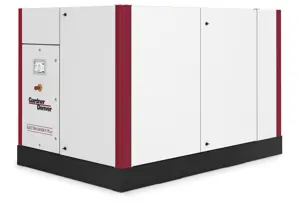

Explore Other Assets


© 2026 MaintainX. All rights reserved.