


East Penn Manufacturing Co. Interlock HT95
Need answers fast?
Explore the manual using AI.
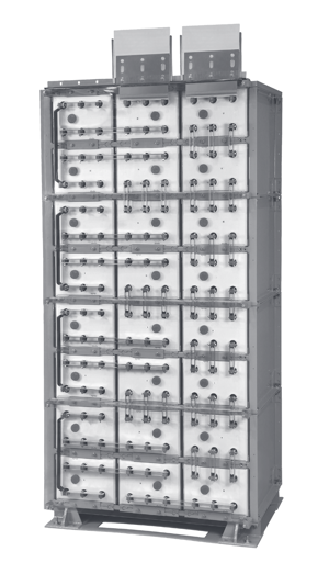
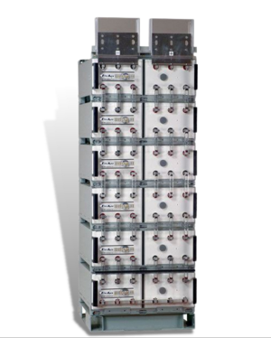
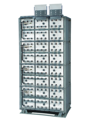
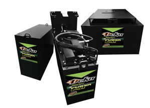
The East Penn Manufacturing Co. Interlock HT95 is a high-performance industrial battery system designed for reliable energy storage and management. This model ensures optimal performance and longevity, making it ideal for various industrial applications. Regular maintenance and quality spare parts are essential for maximizing its efficiency and lifespan.
Turn manuals into instant answers
with your AI-powered assistantTurn manuals into instant answers
with your AI-powered assistant
Manual for East Penn Manufacturing Co. Interlock HT95
Complete asset maintenance, one click away
Get instant access to all the maintenance information you need. Empower technicians to perform preventive maintenance with asset packages, ready to use right out of the box.

Documents & Manuals
Find all the essential guides in one place.
 Tensioning Guide
- Belt-diagram
- C-120 pulleys
+ 13 more

Work Order Templates
Pre-built workflows to keep your asset running smoothly.
- Daily Electrical System Inspection
- Replace Roller and Pulley
- Install Engine B-120
+ 29 more

Procedures
Integrate maintenance plans directly into your work orders.
- Motion Industries
- Applied Industrial Technologies
- Electrical Brothers
+ 5 more

Parts
Access the parts list for your equipment in MaintainX.
- Drive Motor
- B2 Rollers
- Tensioning System
+ 40 more
East Penn Manufacturing Co. Interlock HT95
Create an account to install this asset package.
Maintenance Plans for East Penn Manufacturing Co. Interlock Model HT95
Integrate maintenance plans directly into your work orders in MaintainX.
Replacement
Cell Replacement Procedure
1. Cells develop internal pressure. Relieving this pressure from the cell will make it easier to install the cell into the module. Follow the steps of “Cell Removal Procedure” item 4.
2. Ensure cell polarity is correct prior to installing cell
3. Replace cell retainer bar.
4. Refer to “Electrical Connection” section for installing connectors of replacement cell.
CELL REMOVAL PROCEDURE
1. Before removing cell, review Safety Precautions (pg a.3) of this manual. Contact East Penn with specific questions or concerns.
2. Disconnect Charger and the system ground connection.
3. Remove connectors from cell being removed.

Testing
Acceptance Testing
Each cell should be at 100% State of Charge prior to performing an acceptance test on the battery system. To ensure the cells are fully charged the following charge schedule should be followed.
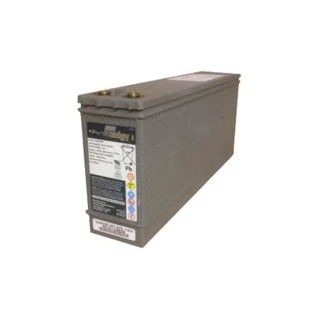
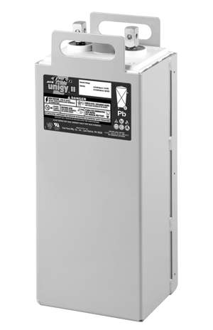
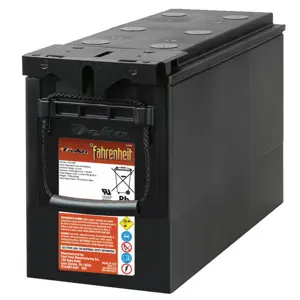
Cells should be charged at the equalization rate of 2.40 volts per cell for 24 hours. Temperature compensated charging parameters shall be applied as detailed in “Voltage Compensation Chart” in Appendix F for Unigy II & Appendix G for Deka Fahrenheit HT 2V of this manual.
To ensure the cells are fully charged within 24hrs the charger used for this charge must have the current equal to the maximum charge current for the given cell type (model), as called out in Appendix F for Unigy II & Appendix G for Deka Fahrenheit HT 2V
If these requirements cannot be met, contact East Penn Reserve Power’s Product Support group for alternate instructions.
Upon completion, the charge voltage should be lowered to the float voltage of 2.25 volts per cell for a minimum period of 72 hours. Reference: IEEE 1188-2005 Section 7.2 for additional acceptance test requirements.
Upon completion of the above charge, the desired acceptance test can be performed.
NOTE: There shall be no discharges of any duration between the start of the equalization and the completion of the float period. If a discharge does occur, the charging regime detailed above shall be repeated.
Upon completion of the acceptance test, the battery system should be placed on float charge at 2.25 volts per cell to restore the battery to its’ rated capacity.
Cleaning
Battery Cleaning
Batteries, cabinets, racks, and modules should be cleaned with clean water. If neutralizing is required use a mixture of 1 lb baking soda to 1 gallon of water or East Penn Mfg. supplied battery cleaner (part # 00321). Use clean water to remove baking soda residue
Never use solvents to clean the battery.
Check
1. For future identification, individual cells should be numbered in electrical connection sequence, beginning with number one (1) at the positive end of the battery string.
NOTE: Following steps are to be followed with battery disconnected from any load or charge source.
2. Read and record the voltages of the individual cells to assure that they are connected properly. The total battery string voltage should be approximately equal to the number of cells connected in series, multiplied by the measured voltage of one cell If the measured is less, recheck the connections for proper polarity. Verify that all cell connections have been properly torqued.
3. Measure and record the intercell connection resistance using a micro-ohms meter. This helps determine the adequacy of initial connection installation and can be used as a reference for future maintenance requirements.
Refer to the “Battery Maintenance Report” form in Appendix K of this manual. Review the records of each connection and detail resistance measurements. Clean, remake, and re-measure any connection that has a resistance measurement greater than 10% of the average of all the same type connections (i.e. intercell, intermodule, etc.).
4. Battery string performance is based on the output at the cell terminals. Therefore, the shortest electrical connection between the battery string and the operating equipment results in maximum total system performance.
Select cable size based on current carrying capability and voltage drop.
Cable size should not provide a greater voltage drop between; the battery string and operating equipment than customer; specified. Excessive voltage drop in cables will reduce the; desired reserve time and power from the battery; string.;
Inspection 1Y
Discharge and recharge affect voltage and ohmic values. These readings should be taken only after the battery string has been on continuous, uninterrupted float charge for at least one month.; The following values should be recorded using the Battery Maintenance Report in Appendix K.
1. Conduct a visual inspection of each cell
2. Battery string voltage at battery terminals while battery is on float.
3. Charger voltage at the charger panel.
4. Individual cell voltages. Cells should be within ± 0.05 volts of the average cell float voltage.
5. Ambient temperatures within area of battery string
6. Average battery string temperature at a minimum of three different cells at varying locations. Temperatures shall be taken at the negative post.
7. Individual cell ohmic readings. To provide accurate/ consistent values, cells must be fully charged, at same temperature and probes placed at; same location each time readings are taken.
On a 4-post cell, place meter leads on the left positive & left negative posts or right positive & right negative posts. For 6-post cells, measure from center positive to center negative posts. Do not measure diagonally from positive to negative posts.; See below example for specific location.
Unlock efficiency
with MaintainX CoPilot
MaintainX CoPilot is your expert colleague, on call 24/7, helping your team find the answers they need to keep equipment running.
Reduce Unplanned Downtime
Ensure your team follows consistent procedures to minimize equipment failures and costly delays.
Maximize Asset Availability
Keep your assets running longer and more reliably, with standardized maintenance workflows from OEM manuals.
Lower Maintenance Costs
Turn any technician into an expert to streamline operations, maintain more assets, and reduce overall costs.
Thousands of companies manage their assets with MaintainX

'%3e%3cpath%20fill='url(%23b)'%20d='M66.008%2080.068c-5.084-.786-9.763-3.834-12.442-8.68a16.942%2016.942%200%200%201-1.87-5.18c1.096.19%202.203.476%203.298.87%206.525%202.333%2010.836%207.68%2011.014%2012.99ZM51.47%2061.576c.488-5.524%203.62-10.716%208.847-13.597a17.132%2017.132%200%200%201%2011.335-1.882c-.798%208.145-7.43%2014.848-16.038%2015.599-1.417.119-2.799.07-4.144-.12Zm28.564-11.478a17.513%2017.513%200%200%201%203.727%204.62c4.608%208.335%201.584%2018.813-6.75%2023.409a16.988%2016.988%200%200%201-4.359%201.679%2019.624%2019.624%200%200%201-3.977-12.776c.346-7.561%204.942-13.931%2011.36-16.932Z'/%3e%3cpath%20fill='%23110F0D'%20fill-rule='evenodd'%20d='M142.831%2048.324h4.977V77.03h-4.977V48.324Zm27.278%2013.002c.322%201.048.453%202.263.453%203.62v12.073h-4.787V66.208c0-.75-.047-1.572-.154-2.143-.453-2.382-1.822-3.572-4.215-3.572-2.31%200-3.882%201.274-4.43%203.476-.143.596-.226%201.405-.226%202.25v10.8h-4.787V56.623h4.477v2.989c1.536-2.5%203.906-3.43%206.371-3.43%203.488%200%206.263%201.68%207.298%205.144Zm24.636%207.323c0%203.882-2.358%206.525-5.763%207.727-1.298.453-2.632.643-4.62.643h-10.169V48.324h9.085c1.691%200%203.156.143%204.049.38%203.465.93%205.727%203.68%205.727%207.335%200%202.441-.81%204.156-2.762%205.644%202.905%201.417%204.453%203.727%204.453%206.966Zm-15.634-8.656h4.584c1.024%200%201.917-.143%202.536-.417%201.215-.548%201.905-1.608%201.905-3.167%200-1.548-.643-2.572-1.845-3.132-.691-.31-1.762-.452-2.763-.452h-4.417v7.168Zm10.716%208.465c0-1.536-.893-3.37-3.227-3.893-.428-.095-1.036-.143-1.571-.143h-5.918v8.085h5.501c.56%200%201.429-.048%201.953-.167%201.94-.453%203.262-1.846%203.262-3.882Zm47.747-11.847-8.097%2020.408h-4.429l-8.109-20.408h5.191l5.192%2014.574%205.108-14.574h5.144Zm-20.218%2010.002c0%20.69-.036%201.262-.155%201.94h-15.943c.631%202.87%202.714%204.728%205.882%204.728%202.131%200%203.607-.882%204.703-2.525h4.87c-1.762%204.144-5.204%206.692-9.657%206.692-6.084%200-10.537-4.858-10.537-10.49%200-6.108%204.524-10.776%2010.335-10.776%206.239%200%2010.442%204.954%2010.502%2010.43Zm-4.763-1.405c-.333-2.846-2.643-4.858-5.691-4.858-2.894%200-5.287%201.929-5.621%204.858h11.312Zm-72.667%203.44c0%204.787-3.287%208.371-9.419%208.371H119.363V64.66c-1.917.274-3.87.69-5.811%201.238l4.537%2011.121h-5.418l-3.596-9.585c-5.144%202.084-10.085%205.216-14.217%209.585h-4.786L101.8%2048.312h4.56l5.68%2013.883a44.112%2044.112%200%200%201%207.323-1.774V48.312h9.084c1.703%200%203.156.143%204.061.393%203.453.929%205.727%203.667%205.727%207.323%200%201.917-.738%204.179-2.81%205.691%203.06%201.56%204.501%204.025%204.501%206.93Zm-15.634-8.667a62.664%2062.664%200%200%201%202.06-.036c1.703.012%203.239.131%204.608.37%201.441-.549%202.357-1.727%202.357-3.537%200-1.941-.881-3.144-2.488-3.667-.548-.18-1.358-.286-2.322-.286h-4.215v7.156Zm-16.55%203.905-3.715-9.894-6.394%2016.502c2.833-2.595%206.263-4.858%2010.109-6.608Zm27.254%204.74c0-2.775-3.131-4.347-8.513-4.418-.715%200-1.441.011-2.191.047v8.252h5.918c2.548%200%204.786-1.37%204.786-3.882Z'%20clip-rule='evenodd'/%3e%3c/g%3e%3cdefs%3e%3clinearGradient%20id='b'%20x1='51.47'%20x2='85.916'%20y1='62.946'%20y2='62.946'%20gradientUnits='userSpaceOnUse'%3e%3cstop%20stop-color='%23CD9F28'/%3e%3cstop%20offset='1'%20stop-color='%23ECD80B'/%3e%3c/linearGradient%3e%3cclipPath%20id='a'%3e%3cpath%20fill='%23fff'%20d='M51.47%2045.728h186.104V80.14H51.47z'/%3e%3c/clipPath%3e%3c/defs%3e%3c/svg%3e)


More from East Penn Manufacturing Co.


Explore Other Assets


© 2026 MaintainX. All rights reserved.