


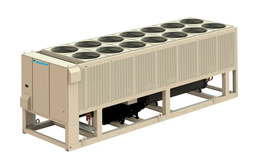
Daikin Screw Chiller AWV024
Need answers fast?
Explore the manual using AI.
Turn manuals into instant answers
with your AI-powered assistantTurn manuals into instant answers
with your AI-powered assistant
Manual for Daikin Screw Chiller AWV024
Complete asset maintenance, one click away
Get instant access to all the maintenance information you need. Empower technicians to perform preventive maintenance with asset packages, ready to use right out of the box.

Documents & Manuals
Find all the essential guides in one place.
 Tensioning Guide
- Belt-diagram
- C-120 pulleys
+ 13 more

Work Order Templates
Pre-built workflows to keep your asset running smoothly.
- Daily Electrical System Inspection
- Replace Roller and Pulley
- Install Engine B-120
+ 29 more

Procedures
Integrate maintenance plans directly into your work orders.
- Motion Industries
- Applied Industrial Technologies
- Electrical Brothers
+ 5 more

Parts
Access the parts list for your equipment in MaintainX.
- Drive Motor
- B2 Rollers
- Tensioning System
+ 40 more
Daikin Screw Chiller AWV024
Create an account to install this asset package.
Maintenance Plans for Daikin Screw Chiller Model AWV024
Integrate maintenance plans directly into your work orders in MaintainX.
Oil Sump Check
Enter the Discharge Temperature
Enter the Saturated Oil Temperature
Oil sump check is set to Ready when: Discharge Temperature > Saturated Oil Temperature + 5°C
Oil sump check is set to Not Ready when: Discharge Temperature < Saturated Oil Temperature + 4.5°C
Is the oil sump check ready?
Sign off on the oil sump check

Oil Filter Disassembling
Warning: After the compressor has been pumped down and isolated, the oil contained inside the filter housing will remain hot enough to cause burns for some time afterwards. Always allow sufficient time for the oil to cool down so that it is cool enough not to be a danger when drained off (less than 35°C is recommended). Severe injury from burns can result.
Compressor pumped out?
Electrical supply to the control panels and compressor motor terminal isolated?
Oil filter assembly components are: - Oil Filter – 250mm - Oil Filter Housing Cover - O-Ring – 89.5x3 - O-Ring – 76.1x3.4 - (6) M8 Bolts
Unscrew and remove two hex head side cover bolts 180° apart. Insert M8 guide studs into the vacant holes.
Remove remaining bolts and oil filter housing cover.
Pull the oil filter off of the spigot and withdraw the oil filter from the housing and clean the housing.
Clean oil filter housing cover plate and all other components.
Sign off on the oil filter disassembling
3 Monthly Epoxy Coated Coils Cleaning
Warning: This cleaning procedure requires trained personnel with PPE!
Quarterly cleaning is essential to extend the life of an epoxy coated coil and is required to maintain warranty coverage.
Surface debris removed?
Coil cleaned with an approved coil cleaner?
Select the cleaning agent used
Chloride remover used to remove soluble salts and revitalize the unit?
Warning: Use caution when applying coil cleaners. They can contain potentially harmful chemicals. Wear breathing apparatus and protective clothing.
Barrier removed prior to application of CHLOR*RID DTS?
CHLOR*RID DTS applied uniformly across the substrate?
Screw Chiller Pre-Start Check
Chilled Water:
- Piping Complete
- Water strainer installed on evaporator, 0.125” (3.2mm) or smaller perforations
- Water System filled, flushed and vented
- Pumps installed and operational (rotation checked, strainers cleaned)
- Controls operational (3-way valves, face/bypass dampers, bypass valves, etc.)
- Water system operated and tested; flow meets unit design requirements
- Flow switch installed and wired
- Vent installed on evaporator
Screw Chiller Pre-Startup Inspection
NOTICE: Daikin Applied service personnel or factory authorized service agency must perform initial startup in order to activate warranty. Return the “Screw Compressor Equipment Warranty Form” within 10 working days to Daikin Applied as instructed on the form to obtain full warranty benefits.
CAUTION: Most relays and terminals in the unit control center are powered when S1 is closed and the control circuit disconnect is on. Therefore, do not close S1 until ready for startup or the unit may start unintentionally and possibly cause equipment damage.
Inspect the chiller to ensure no components became loose or damaged during shipping or installation, including leak test and wiring check.
Double check that the discharge shutoff valve and the optional compressor suction butterfly valves are open.
Check that the manual liquid line shutoff valves at the outlet of the subcooler coils are open.
Check the leaving chilled water temperature set point on the MicroTech® III controller to be sure it is set at the desired chilled water temperature.
Start the auxiliary equipment for the installation by turning on the time clock, and/or remote on/off switch, and chilled water pump.
Check to see that pumpdown switches Q1 and Q2 are in the “Pumpdown and Stop” (open) position. Throw the S1 switch to the “Auto” position.
Under the “Control Mode” menu of the keypad, place the unit into the automatic Cool Mode.
Parts for Daikin Screw Chiller AWV024
Access the parts list for your equipment in MaintainX.
AWG Wire Gauge
83754
AWG Wire
83804
Enviro-Coil Concentrate, Hydro-Balance Corp P.O. Box 730 Prosper, TX 75078 800-527-5166
H-EC01
Chloride Remover, Chlor*Rid Int’l, Inc. P.O. Box 908 Chandler, AZ 85244 800-422-3217
Chlor*Rid DTS
AWG Wire Gauge
83754
AWG Wire
83804
Enviro-Coil Concentrate, Hydro-Balance Corp P.O. Box 730 Prosper, TX 75078 800-527-5166
H-EC01
Chloride Remover, Chlor*Rid Int’l, Inc. P.O. Box 908 Chandler, AZ 85244 800-422-3217
Chlor*Rid DTS
AWG Wire Gauge
83754
AWG Wire
83804
Enviro-Coil Concentrate, Hydro-Balance Corp P.O. Box 730 Prosper, TX 75078 800-527-5166
H-EC01
Chloride Remover, Chlor*Rid Int’l, Inc. P.O. Box 908 Chandler, AZ 85244 800-422-3217
Chlor*Rid DTS
Unlock efficiency
with MaintainX CoPilot
MaintainX CoPilot is your expert colleague, on call 24/7, helping your team find the answers they need to keep equipment running.
Reduce Unplanned Downtime
Ensure your team follows consistent procedures to minimize equipment failures and costly delays.
Maximize Asset Availability
Keep your assets running longer and more reliably, with standardized maintenance workflows from OEM manuals.
Lower Maintenance Costs
Turn any technician into an expert to streamline operations, maintain more assets, and reduce overall costs.
Thousands of companies manage their assets with MaintainX

'%3e%3cpath%20fill='url(%23b)'%20d='M66.008%2080.068c-5.084-.786-9.763-3.834-12.442-8.68a16.942%2016.942%200%200%201-1.87-5.18c1.096.19%202.203.476%203.298.87%206.525%202.333%2010.836%207.68%2011.014%2012.99ZM51.47%2061.576c.488-5.524%203.62-10.716%208.847-13.597a17.132%2017.132%200%200%201%2011.335-1.882c-.798%208.145-7.43%2014.848-16.038%2015.599-1.417.119-2.799.07-4.144-.12Zm28.564-11.478a17.513%2017.513%200%200%201%203.727%204.62c4.608%208.335%201.584%2018.813-6.75%2023.409a16.988%2016.988%200%200%201-4.359%201.679%2019.624%2019.624%200%200%201-3.977-12.776c.346-7.561%204.942-13.931%2011.36-16.932Z'/%3e%3cpath%20fill='%23110F0D'%20fill-rule='evenodd'%20d='M142.831%2048.324h4.977V77.03h-4.977V48.324Zm27.278%2013.002c.322%201.048.453%202.263.453%203.62v12.073h-4.787V66.208c0-.75-.047-1.572-.154-2.143-.453-2.382-1.822-3.572-4.215-3.572-2.31%200-3.882%201.274-4.43%203.476-.143.596-.226%201.405-.226%202.25v10.8h-4.787V56.623h4.477v2.989c1.536-2.5%203.906-3.43%206.371-3.43%203.488%200%206.263%201.68%207.298%205.144Zm24.636%207.323c0%203.882-2.358%206.525-5.763%207.727-1.298.453-2.632.643-4.62.643h-10.169V48.324h9.085c1.691%200%203.156.143%204.049.38%203.465.93%205.727%203.68%205.727%207.335%200%202.441-.81%204.156-2.762%205.644%202.905%201.417%204.453%203.727%204.453%206.966Zm-15.634-8.656h4.584c1.024%200%201.917-.143%202.536-.417%201.215-.548%201.905-1.608%201.905-3.167%200-1.548-.643-2.572-1.845-3.132-.691-.31-1.762-.452-2.763-.452h-4.417v7.168Zm10.716%208.465c0-1.536-.893-3.37-3.227-3.893-.428-.095-1.036-.143-1.571-.143h-5.918v8.085h5.501c.56%200%201.429-.048%201.953-.167%201.94-.453%203.262-1.846%203.262-3.882Zm47.747-11.847-8.097%2020.408h-4.429l-8.109-20.408h5.191l5.192%2014.574%205.108-14.574h5.144Zm-20.218%2010.002c0%20.69-.036%201.262-.155%201.94h-15.943c.631%202.87%202.714%204.728%205.882%204.728%202.131%200%203.607-.882%204.703-2.525h4.87c-1.762%204.144-5.204%206.692-9.657%206.692-6.084%200-10.537-4.858-10.537-10.49%200-6.108%204.524-10.776%2010.335-10.776%206.239%200%2010.442%204.954%2010.502%2010.43Zm-4.763-1.405c-.333-2.846-2.643-4.858-5.691-4.858-2.894%200-5.287%201.929-5.621%204.858h11.312Zm-72.667%203.44c0%204.787-3.287%208.371-9.419%208.371H119.363V64.66c-1.917.274-3.87.69-5.811%201.238l4.537%2011.121h-5.418l-3.596-9.585c-5.144%202.084-10.085%205.216-14.217%209.585h-4.786L101.8%2048.312h4.56l5.68%2013.883a44.112%2044.112%200%200%201%207.323-1.774V48.312h9.084c1.703%200%203.156.143%204.061.393%203.453.929%205.727%203.667%205.727%207.323%200%201.917-.738%204.179-2.81%205.691%203.06%201.56%204.501%204.025%204.501%206.93Zm-15.634-8.667a62.664%2062.664%200%200%201%202.06-.036c1.703.012%203.239.131%204.608.37%201.441-.549%202.357-1.727%202.357-3.537%200-1.941-.881-3.144-2.488-3.667-.548-.18-1.358-.286-2.322-.286h-4.215v7.156Zm-16.55%203.905-3.715-9.894-6.394%2016.502c2.833-2.595%206.263-4.858%2010.109-6.608Zm27.254%204.74c0-2.775-3.131-4.347-8.513-4.418-.715%200-1.441.011-2.191.047v8.252h5.918c2.548%200%204.786-1.37%204.786-3.882Z'%20clip-rule='evenodd'/%3e%3c/g%3e%3cdefs%3e%3clinearGradient%20id='b'%20x1='51.47'%20x2='85.916'%20y1='62.946'%20y2='62.946'%20gradientUnits='userSpaceOnUse'%3e%3cstop%20stop-color='%23CD9F28'/%3e%3cstop%20offset='1'%20stop-color='%23ECD80B'/%3e%3c/linearGradient%3e%3cclipPath%20id='a'%3e%3cpath%20fill='%23fff'%20d='M51.47%2045.728h186.104V80.14H51.47z'/%3e%3c/clipPath%3e%3c/defs%3e%3c/svg%3e)


More from Daikin


Explore Other Assets


© 2026 MaintainX. All rights reserved.