


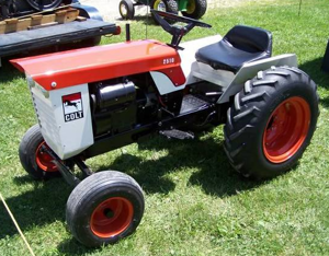
Case Tractor FARMALL JX 90 DT
Need answers fast?
Explore the manual using AI.

Turn manuals into instant answers
with your AI-powered assistantTurn manuals into instant answers
with your AI-powered assistant
Manual for Case Tractor FARMALL JX 90 DT
Complete asset maintenance, one click away
Get instant access to all the maintenance information you need. Empower technicians to perform preventive maintenance with asset packages, ready to use right out of the box.

Documents & Manuals
Find all the essential guides in one place.
 Tensioning Guide
- Belt-diagram
- C-120 pulleys
+ 13 more

Work Order Templates
Pre-built workflows to keep your asset running smoothly.
- Daily Electrical System Inspection
- Replace Roller and Pulley
- Install Engine B-120
+ 29 more

Procedures
Integrate maintenance plans directly into your work orders.
- Motion Industries
- Applied Industrial Technologies
- Electrical Brothers
+ 5 more

Parts
Access the parts list for your equipment in MaintainX.
- Drive Motor
- B2 Rollers
- Tensioning System
+ 40 more
Case Tractor FARMALL JX 90 DT
Create an account to install this asset package.
Maintenance Plans for Case Tractor Model FARMALL JX 90 DT
Integrate maintenance plans directly into your work orders in MaintainX.
Engine Valves Maintenance
WARNING: Handle all parts carefully. Do not put your hands or fingers between parts. Wear suitable safety clothing, safety goggles, gloves and footwear.
Clean all parts carefully before carrying out the following operations.
Use tool 380000302 for valve removal and installation.
Minor sealing faults present?
In case of minor sealing faults, the valves and their seats in the cylinder head may be re--faced using a pneumatic grinder or universal grinder.
Serious defects present?
In case of more serious defects, re -face the seats and grind the valves as shown in the relative chapter.
Enter the step below the valve contact band measurement
After grinding, check that the step below the valve contact band is no less than 0.5 mm (0.02 in.).

Field Windins Test
To easily and quickly trouble--shoot the starting system problems and reach conclusive results, it is recommended that you use a battery/starting tester (high discharge multimeter) with incorporated 0--20V voltmeter and 0--500 A ammeter.
When using testing devices, follow test procedures recommended by the manufacturer. If you do not have access to testing devices, carry out the following test using a normal 0--20V voltmeter and a 0--500 Amp ammeter in order to check correct starter motor functioning without removing it from the engine.
Before carrying out the test:
- check the battery is fully charged
- check that no wires in the starting system are broken or frayed and that there are no loose connections
- check the engine is not seized.
1. To test field winding insulation, connect an ohmmeter to each of the coil brushes in turn and to a clean and unpainted area of the casing. There should be no readings, that is, there should be no continuity.
2. To test coil continuity, connect an ohmmeter to each of the coil brushes in turn and to the main power clamp (biggest braided wire). Thereading should be 1 Ω.
3. If there is a failure in the field windings, then it will be necessary to change the whole box and field winding system.;
Bench Overhaul
WARNING: Handle all parts with great care. Do not place hands or fingers between one part and another. Always wear the prescribed safety clothing, including protective glasses, gloves and shoes.
Place the PTO unit in the vice on the work bench
Use a punch to straighten the corrugations on the ring nut that retains the driven shaft components
Remove the ring nut from the driven shaft
Remove the four PTO unit internal support fixing screws
Remove the pin securing the fork rod
Withdraw the rod from the rear cover
Partially withdraw the PTO output shaft and remove the internal support together with the drive shaft, the driven gears, the sleeve and the engagement/disengagement/neutral control fork of the 540/750 PTO. Also, retain the thrust washer from the gear for reuse during reassembly
Remove the rear bearing thrust washer and remove the secondary shaft complete with PTO output shaft
Ring Bevel Gear Bearings Adjustment
Warning: Handle all parts with great care. Never place your hands or fingers between one part and another. Wear the prescribed safety clothing, including glasses, gloves and protective footwear.
Warning: Always use appropriate tools to align the holes. NEVER USE YOUR FINGERS OR HANDS.
Bevel pinion fitted and differential assembly inserted
Right and left hand supports secured on the gearbox transmission casing
Ring nuts brought into contact with the races of the bearings
Right and left hand ring nuts slightly screwed onto the support
Radial clearance on the sides of the bevel drive teeth
Clearance of 0.18 mm achieved
Setting high -- low backlash done correctly
1 Yearly Compressor Oil Change
Warning --The oil in the compressor of the recovery/recycling station should be replaced with new oil (code 293825) every 12 months to maintain the station’s refrigerant treatment capacity and to protect the compressor.
Open cock (13), and drain the oil into a container to be disposed of in accordance with local regulations for waste oil disposal.
Close cock (13).
Remove the caps from the service valves (14) on the side of the compressor and (13) on the sight glass.
Connect the service pipe of the evacuation station (294030) to valve (14) and connect a pick--up pipe from kit 294043to valve (13) on the sight glass.
Perform the evacuation operation with the pump in operation. The new oil can be aspirated from an external container by means of the pick--up pipe.
Once the compressor has been filled with correct quantity of oil (half--way up the sight glass) close valve (13), disconnect the pick--up pipe, and replace the cap on service valve (13). Continue the evacuation for approx. 30 minutes.
On conclusion, close the cocks, switch off the pump, disconnect the service pipe and replace the cap on service valve (14).
Record the operation on the appropriate service report card.
Parts for Case Tractor FARMALL JX 90 DT
Access the parts list for your equipment in MaintainX.
Tractor Dismantling Stand
380000236
Engine Lifting Hook
380000216
Rotating Engine Service Stand
380000301
Engine Mounting Brackets (For Rotating Stand 380000301)
380000313
Compression Test Kit (Complete With Dummy Injector 380000617)
380000303
Tractor Dismantling Stand
380000236
Engine Lifting Hook
380000216
Rotating Engine Service Stand
380000301
Engine Mounting Brackets (For Rotating Stand 380000301)
380000313
Compression Test Kit (Complete With Dummy Injector 380000617)
380000303
Tractor Dismantling Stand
380000236
Engine Lifting Hook
380000216
Rotating Engine Service Stand
380000301
Engine Mounting Brackets (For Rotating Stand 380000301)
380000313
Compression Test Kit (Complete With Dummy Injector 380000617)
380000303
Unlock efficiency
with MaintainX CoPilot
MaintainX CoPilot is your expert colleague, on call 24/7, helping your team find the answers they need to keep equipment running.
Reduce Unplanned Downtime
Ensure your team follows consistent procedures to minimize equipment failures and costly delays.
Maximize Asset Availability
Keep your assets running longer and more reliably, with standardized maintenance workflows from OEM manuals.
Lower Maintenance Costs
Turn any technician into an expert to streamline operations, maintain more assets, and reduce overall costs.
Thousands of companies manage their assets with MaintainX

'%3e%3cpath%20fill='url(%23b)'%20d='M66.008%2080.068c-5.084-.786-9.763-3.834-12.442-8.68a16.942%2016.942%200%200%201-1.87-5.18c1.096.19%202.203.476%203.298.87%206.525%202.333%2010.836%207.68%2011.014%2012.99ZM51.47%2061.576c.488-5.524%203.62-10.716%208.847-13.597a17.132%2017.132%200%200%201%2011.335-1.882c-.798%208.145-7.43%2014.848-16.038%2015.599-1.417.119-2.799.07-4.144-.12Zm28.564-11.478a17.513%2017.513%200%200%201%203.727%204.62c4.608%208.335%201.584%2018.813-6.75%2023.409a16.988%2016.988%200%200%201-4.359%201.679%2019.624%2019.624%200%200%201-3.977-12.776c.346-7.561%204.942-13.931%2011.36-16.932Z'/%3e%3cpath%20fill='%23110F0D'%20fill-rule='evenodd'%20d='M142.831%2048.324h4.977V77.03h-4.977V48.324Zm27.278%2013.002c.322%201.048.453%202.263.453%203.62v12.073h-4.787V66.208c0-.75-.047-1.572-.154-2.143-.453-2.382-1.822-3.572-4.215-3.572-2.31%200-3.882%201.274-4.43%203.476-.143.596-.226%201.405-.226%202.25v10.8h-4.787V56.623h4.477v2.989c1.536-2.5%203.906-3.43%206.371-3.43%203.488%200%206.263%201.68%207.298%205.144Zm24.636%207.323c0%203.882-2.358%206.525-5.763%207.727-1.298.453-2.632.643-4.62.643h-10.169V48.324h9.085c1.691%200%203.156.143%204.049.38%203.465.93%205.727%203.68%205.727%207.335%200%202.441-.81%204.156-2.762%205.644%202.905%201.417%204.453%203.727%204.453%206.966Zm-15.634-8.656h4.584c1.024%200%201.917-.143%202.536-.417%201.215-.548%201.905-1.608%201.905-3.167%200-1.548-.643-2.572-1.845-3.132-.691-.31-1.762-.452-2.763-.452h-4.417v7.168Zm10.716%208.465c0-1.536-.893-3.37-3.227-3.893-.428-.095-1.036-.143-1.571-.143h-5.918v8.085h5.501c.56%200%201.429-.048%201.953-.167%201.94-.453%203.262-1.846%203.262-3.882Zm47.747-11.847-8.097%2020.408h-4.429l-8.109-20.408h5.191l5.192%2014.574%205.108-14.574h5.144Zm-20.218%2010.002c0%20.69-.036%201.262-.155%201.94h-15.943c.631%202.87%202.714%204.728%205.882%204.728%202.131%200%203.607-.882%204.703-2.525h4.87c-1.762%204.144-5.204%206.692-9.657%206.692-6.084%200-10.537-4.858-10.537-10.49%200-6.108%204.524-10.776%2010.335-10.776%206.239%200%2010.442%204.954%2010.502%2010.43Zm-4.763-1.405c-.333-2.846-2.643-4.858-5.691-4.858-2.894%200-5.287%201.929-5.621%204.858h11.312Zm-72.667%203.44c0%204.787-3.287%208.371-9.419%208.371H119.363V64.66c-1.917.274-3.87.69-5.811%201.238l4.537%2011.121h-5.418l-3.596-9.585c-5.144%202.084-10.085%205.216-14.217%209.585h-4.786L101.8%2048.312h4.56l5.68%2013.883a44.112%2044.112%200%200%201%207.323-1.774V48.312h9.084c1.703%200%203.156.143%204.061.393%203.453.929%205.727%203.667%205.727%207.323%200%201.917-.738%204.179-2.81%205.691%203.06%201.56%204.501%204.025%204.501%206.93Zm-15.634-8.667a62.664%2062.664%200%200%201%202.06-.036c1.703.012%203.239.131%204.608.37%201.441-.549%202.357-1.727%202.357-3.537%200-1.941-.881-3.144-2.488-3.667-.548-.18-1.358-.286-2.322-.286h-4.215v7.156Zm-16.55%203.905-3.715-9.894-6.394%2016.502c2.833-2.595%206.263-4.858%2010.109-6.608Zm27.254%204.74c0-2.775-3.131-4.347-8.513-4.418-.715%200-1.441.011-2.191.047v8.252h5.918c2.548%200%204.786-1.37%204.786-3.882Z'%20clip-rule='evenodd'/%3e%3c/g%3e%3cdefs%3e%3clinearGradient%20id='b'%20x1='51.47'%20x2='85.916'%20y1='62.946'%20y2='62.946'%20gradientUnits='userSpaceOnUse'%3e%3cstop%20stop-color='%23CD9F28'/%3e%3cstop%20offset='1'%20stop-color='%23ECD80B'/%3e%3c/linearGradient%3e%3cclipPath%20id='a'%3e%3cpath%20fill='%23fff'%20d='M51.47%2045.728h186.104V80.14H51.47z'/%3e%3c/clipPath%3e%3c/defs%3e%3c/svg%3e)


More from Case


Explore Other Assets


© 2026 MaintainX. All rights reserved.