


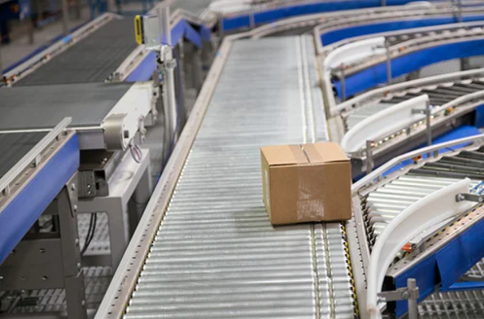
Bastian Solutions Conveyor RLVDC
Need answers fast?
Explore the manual using AI.
Turn manuals into instant answers
with your AI-powered assistantTurn manuals into instant answers
with your AI-powered assistant
Complete asset maintenance, one click away
Get instant access to all the maintenance information you need. Empower technicians to perform preventive maintenance with asset packages, ready to use right out of the box.

Documents & Manuals
Find all the essential guides in one place.
 Tensioning Guide
- Belt-diagram
- C-120 pulleys
+ 13 more

Work Order Templates
Pre-built workflows to keep your asset running smoothly.
- Daily Electrical System Inspection
- Replace Roller and Pulley
- Install Engine B-120
+ 29 more

Procedures
Integrate maintenance plans directly into your work orders.
- Motion Industries
- Applied Industrial Technologies
- Electrical Brothers
+ 5 more

Parts
Access the parts list for your equipment in MaintainX.
- Drive Motor
- B2 Rollers
- Tensioning System
+ 40 more
Bastian Solutions Conveyor RLVDC
Create an account to install this asset package.
Maintenance Plans for Bastian Solutions Conveyor Model RLVDC
Integrate maintenance plans directly into your work orders in MaintainX.
Electrical Maintenance
• All Bastian Solutions’ conveyor DC products operate at either 24V or 48V, nominally.
NOTE: When performing electrical work on Bastian Solutions conveyor, ensure adherence to all applicable OSHA standards.
• If adjustment of control card settings is required, refer to the respective technical manual listed in Reference Documents, or contact Bastian Solutions Customer Service at ConveyorSupport@bastiansolutions.com.
• If there is a need to replace a DC control card, perform the following:
o De-energize associated power supply and remove respective side cover (if applicable)
o Adjust settings of replacement control card to match those of the existing control card.
o Remove the existing control card from the side frame for ease of cable disconnection:
If the existing control card has a mounting plate, remove wiz nut securing control card mounting plate to side frame.
If the existing control card is secured to the conveyor side frame with anything other than a mounting plate, install new securing material on the new control card and reuse the securing material on the side frame.

Standard Roller Replacement
NOTE: If polyvee bands or 2” roller spacing is being used, it will often be easier to remove a roller/band by disassembling the zone roller-by-roller until reaching the roller/ band that is being replaced. The directions in this segment refer to replacement of rollers within a 3” roller center conveyor.
Followed the lockout/tagout procedure in place to ensure safety
Removed the side cover from the intended work area
Applied pressure on the end of the hex shaft opposite the wiring using a small diameter punch or similar tool until the shaft clears the frame
Provided upward force on the roller body until the hex is sitting above the side frame
Removed the hex shaft from the opposite hex hole
Pulled the roller away from the bands until the roller is completely free of the side frames and bands
Slid the new roller through the bands
Once the new roller is through both bands, guided the hex shaft into the hex hole
Motor Driven Roller Replacement
NOTE: If polyvee bands or 2” roller spacing is being used, it will often be easier to remove a roller/band by disassembling the zone roller-by-roller until reaching the roller/ band that is being replaced. The directions in this segment refer to replacement of rollers within a 3” roller center conveyor.
Followed the lockout/tagout procedure in place to ensure safety
Removed the side cover from the intended work area
Loosened the MDR nut located on the cable side of the roller
Pulled the MDR bracket away from the frame
Applied pressure on the end of the hex shaft opposite the cable using a small diameter punch or similar tool until the shaft clears the frame
Provided upward force on the roller body until the hex is sitting above the side frame
Pulled the threaded shaft out of the side frame
Pulled the MDR away from the bands until the MDR is completely free of the side frames and bands
6 Monthly Conveyor Maintenance
Auditory inspection of the equipment
Check all nuts and bolts
Enter the torque reading from the torque wrench
Select the type of MDR
Inspection of O-rings, poly-v bands, and any other bands
Upload a photo of the replaced parts
Sign off on the conveyor maintenance
Band Replacement
Follow the lockout/tagout procedure in place to ensure safety
Remove the side cover from the intended work area
Remove the two rollers within the brackets if the band being replaced is on the outside groove/hub of the roller
Slide one of the removed rollers through the band in circle 1 of Figure 7
Slide the new band onto the same roller on the groove side of the roller
Use the new band to help guide the hex shaft into the hex hole
Insert the opposite side hex shaft into the appropriate hex hole
Install the second roller
Slide the roller through the old band in circle 3 of Figure 7. Then slide the roller through the new band
Unlock efficiency
with MaintainX CoPilot
MaintainX CoPilot is your expert colleague, on call 24/7, helping your team find the answers they need to keep equipment running.
Reduce Unplanned Downtime
Ensure your team follows consistent procedures to minimize equipment failures and costly delays.
Maximize Asset Availability
Keep your assets running longer and more reliably, with standardized maintenance workflows from OEM manuals.
Lower Maintenance Costs
Turn any technician into an expert to streamline operations, maintain more assets, and reduce overall costs.
Thousands of companies manage their assets with MaintainX

'%3e%3cpath%20fill='url(%23b)'%20d='M66.008%2080.068c-5.084-.786-9.763-3.834-12.442-8.68a16.942%2016.942%200%200%201-1.87-5.18c1.096.19%202.203.476%203.298.87%206.525%202.333%2010.836%207.68%2011.014%2012.99ZM51.47%2061.576c.488-5.524%203.62-10.716%208.847-13.597a17.132%2017.132%200%200%201%2011.335-1.882c-.798%208.145-7.43%2014.848-16.038%2015.599-1.417.119-2.799.07-4.144-.12Zm28.564-11.478a17.513%2017.513%200%200%201%203.727%204.62c4.608%208.335%201.584%2018.813-6.75%2023.409a16.988%2016.988%200%200%201-4.359%201.679%2019.624%2019.624%200%200%201-3.977-12.776c.346-7.561%204.942-13.931%2011.36-16.932Z'/%3e%3cpath%20fill='%23110F0D'%20fill-rule='evenodd'%20d='M142.831%2048.324h4.977V77.03h-4.977V48.324Zm27.278%2013.002c.322%201.048.453%202.263.453%203.62v12.073h-4.787V66.208c0-.75-.047-1.572-.154-2.143-.453-2.382-1.822-3.572-4.215-3.572-2.31%200-3.882%201.274-4.43%203.476-.143.596-.226%201.405-.226%202.25v10.8h-4.787V56.623h4.477v2.989c1.536-2.5%203.906-3.43%206.371-3.43%203.488%200%206.263%201.68%207.298%205.144Zm24.636%207.323c0%203.882-2.358%206.525-5.763%207.727-1.298.453-2.632.643-4.62.643h-10.169V48.324h9.085c1.691%200%203.156.143%204.049.38%203.465.93%205.727%203.68%205.727%207.335%200%202.441-.81%204.156-2.762%205.644%202.905%201.417%204.453%203.727%204.453%206.966Zm-15.634-8.656h4.584c1.024%200%201.917-.143%202.536-.417%201.215-.548%201.905-1.608%201.905-3.167%200-1.548-.643-2.572-1.845-3.132-.691-.31-1.762-.452-2.763-.452h-4.417v7.168Zm10.716%208.465c0-1.536-.893-3.37-3.227-3.893-.428-.095-1.036-.143-1.571-.143h-5.918v8.085h5.501c.56%200%201.429-.048%201.953-.167%201.94-.453%203.262-1.846%203.262-3.882Zm47.747-11.847-8.097%2020.408h-4.429l-8.109-20.408h5.191l5.192%2014.574%205.108-14.574h5.144Zm-20.218%2010.002c0%20.69-.036%201.262-.155%201.94h-15.943c.631%202.87%202.714%204.728%205.882%204.728%202.131%200%203.607-.882%204.703-2.525h4.87c-1.762%204.144-5.204%206.692-9.657%206.692-6.084%200-10.537-4.858-10.537-10.49%200-6.108%204.524-10.776%2010.335-10.776%206.239%200%2010.442%204.954%2010.502%2010.43Zm-4.763-1.405c-.333-2.846-2.643-4.858-5.691-4.858-2.894%200-5.287%201.929-5.621%204.858h11.312Zm-72.667%203.44c0%204.787-3.287%208.371-9.419%208.371H119.363V64.66c-1.917.274-3.87.69-5.811%201.238l4.537%2011.121h-5.418l-3.596-9.585c-5.144%202.084-10.085%205.216-14.217%209.585h-4.786L101.8%2048.312h4.56l5.68%2013.883a44.112%2044.112%200%200%201%207.323-1.774V48.312h9.084c1.703%200%203.156.143%204.061.393%203.453.929%205.727%203.667%205.727%207.323%200%201.917-.738%204.179-2.81%205.691%203.06%201.56%204.501%204.025%204.501%206.93Zm-15.634-8.667a62.664%2062.664%200%200%201%202.06-.036c1.703.012%203.239.131%204.608.37%201.441-.549%202.357-1.727%202.357-3.537%200-1.941-.881-3.144-2.488-3.667-.548-.18-1.358-.286-2.322-.286h-4.215v7.156Zm-16.55%203.905-3.715-9.894-6.394%2016.502c2.833-2.595%206.263-4.858%2010.109-6.608Zm27.254%204.74c0-2.775-3.131-4.347-8.513-4.418-.715%200-1.441.011-2.191.047v8.252h5.918c2.548%200%204.786-1.37%204.786-3.882Z'%20clip-rule='evenodd'/%3e%3c/g%3e%3cdefs%3e%3clinearGradient%20id='b'%20x1='51.47'%20x2='85.916'%20y1='62.946'%20y2='62.946'%20gradientUnits='userSpaceOnUse'%3e%3cstop%20stop-color='%23CD9F28'/%3e%3cstop%20offset='1'%20stop-color='%23ECD80B'/%3e%3c/linearGradient%3e%3cclipPath%20id='a'%3e%3cpath%20fill='%23fff'%20d='M51.47%2045.728h186.104V80.14H51.47z'/%3e%3c/clipPath%3e%3c/defs%3e%3c/svg%3e)


More from Bastian Solutions
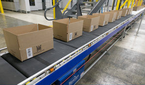
Explore Other Assets


© 2026 MaintainX. All rights reserved.