


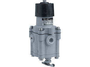
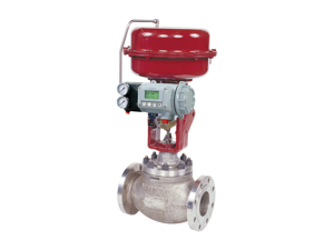
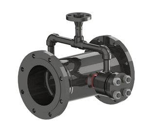
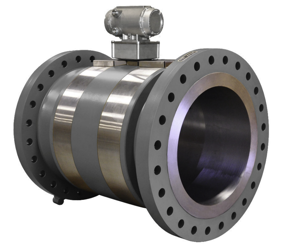
Baker Hughes Safety Relief Valve 1982 Series
Need answers fast?
Explore the manual using AI.
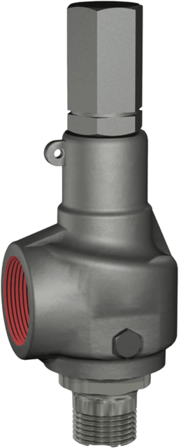
The Baker Hughes Safety Relief Valve 1982 Series is a critical asset designed for pressure relief applications in industrial settings. Known for its reliability and efficiency, this valve ensures safety by preventing overpressure conditions, making it essential for maintaining operational integrity in various processes.
Turn manuals into instant answers
with your AI-powered assistantTurn manuals into instant answers
with your AI-powered assistant
Manual for Baker Hughes Safety Relief Valve 1982 Series
Complete asset maintenance, one click away
Get instant access to all the maintenance information you need. Empower technicians to perform preventive maintenance with asset packages, ready to use right out of the box.

Documents & Manuals
Find all the essential guides in one place.
 Tensioning Guide
- Belt-diagram
- C-120 pulleys
+ 13 more

Work Order Templates
Pre-built workflows to keep your asset running smoothly.
- Daily Electrical System Inspection
- Replace Roller and Pulley
- Install Engine B-120
+ 29 more

Procedures
Integrate maintenance plans directly into your work orders.
- Motion Industries
- Applied Industrial Technologies
- Electrical Brothers
+ 5 more

Parts
Access the parts list for your equipment in MaintainX.
- Drive Motor
- B2 Rollers
- Tensioning System
+ 40 more
Baker Hughes Safety Relief Valve 1982 Series
Create an account to install this asset package.
Maintenance Plans for Baker Hughes Safety Relief Valve Model 1982 Series
Integrate maintenance plans directly into your work orders in MaintainX.
1 Yearly Maintenance
A 12-month maintenance interval is recommended for general service conditions. For severe service applications, a 3 to 6 month inspection and testing interim may be more appropriate. The specific plant’s operating and service history will better determine this frequency. Baker Hughes encourages preventive maintenance. Occasionally, remachining may be necessary to extend the service life of a valve. Keep all parts for each valve separated to ensure replacement in the same valve.
DANGER: Insure there is no pressure in the inlet of the valve before attempting to remove it from the piping system.
Note: For maintenance questions not covered in this manual, please contact your local Green Tag Center (GTC).;

Adjusting Ring Replacement
"Adjusting Ring should be replaced if: a. Inside diameter (A) exceeds maximum dimension or nicked.
b. Outside diameter (B) is below minimum dimension or nicked.
c. Threads (T) should be replaced if torn, galled or stripped.
d. Adjusting ring notches (N) are worn or missing.
f. Exceeds dimensions mentioned in Table 4 and Figure 8.;"
Base Replacement
Base should be replaced if: a. Seat (Surface X) is nicked, or dimension D minimum has been exceeded. (See Table 2).
b. Threads (T) are torn, galled or stripped.
c. Gasket surface (G) is nicked or experiencing leakage.
d. Exceeds other dimensions in Table 2 and Figure 6.;
Adjusting Screw Replacement
"Adjusting Screw should be replaced if: a. Threads (T) are torn, galled and stripped.
b. Bearing surfaces (A) are galled or pitted.;"
Disc Replacement
"Guide should be replaced if: a. Inside diameter (A) exceeds maximum dimension or galled. It requires 32 RMS finish.
b. Threads (T) should be replaced if torn, galled or stripped. c. Overall condition is distorted or egged.
d. Guide weld (W) is cracked weld or loose guide.
Note: Guide is tack welded to the bonnet, do not attempt to remove from bonnet.;"
Parts for Baker Hughes Safety Relief Valve 1982 Series
Access the parts list for your equipment in MaintainX.
Bushing
-
Cam Shaft
-
Sealing Plug Gasket
-
Inlet Flange
-
Adjusting Screw
-
Bushing
-
Cam Shaft
-
Sealing Plug Gasket
-
Inlet Flange
-
Adjusting Screw
-
Bushing
-
Cam Shaft
-
Sealing Plug Gasket
-
Inlet Flange
-
Adjusting Screw
-
Unlock efficiency
with MaintainX CoPilot
MaintainX CoPilot is your expert colleague, on call 24/7, helping your team find the answers they need to keep equipment running.
Reduce Unplanned Downtime
Ensure your team follows consistent procedures to minimize equipment failures and costly delays.
Maximize Asset Availability
Keep your assets running longer and more reliably, with standardized maintenance workflows from OEM manuals.
Lower Maintenance Costs
Turn any technician into an expert to streamline operations, maintain more assets, and reduce overall costs.
Thousands of companies manage their assets with MaintainX

'%3e%3cpath%20fill='url(%23b)'%20d='M66.008%2080.068c-5.084-.786-9.763-3.834-12.442-8.68a16.942%2016.942%200%200%201-1.87-5.18c1.096.19%202.203.476%203.298.87%206.525%202.333%2010.836%207.68%2011.014%2012.99ZM51.47%2061.576c.488-5.524%203.62-10.716%208.847-13.597a17.132%2017.132%200%200%201%2011.335-1.882c-.798%208.145-7.43%2014.848-16.038%2015.599-1.417.119-2.799.07-4.144-.12Zm28.564-11.478a17.513%2017.513%200%200%201%203.727%204.62c4.608%208.335%201.584%2018.813-6.75%2023.409a16.988%2016.988%200%200%201-4.359%201.679%2019.624%2019.624%200%200%201-3.977-12.776c.346-7.561%204.942-13.931%2011.36-16.932Z'/%3e%3cpath%20fill='%23110F0D'%20fill-rule='evenodd'%20d='M142.831%2048.324h4.977V77.03h-4.977V48.324Zm27.278%2013.002c.322%201.048.453%202.263.453%203.62v12.073h-4.787V66.208c0-.75-.047-1.572-.154-2.143-.453-2.382-1.822-3.572-4.215-3.572-2.31%200-3.882%201.274-4.43%203.476-.143.596-.226%201.405-.226%202.25v10.8h-4.787V56.623h4.477v2.989c1.536-2.5%203.906-3.43%206.371-3.43%203.488%200%206.263%201.68%207.298%205.144Zm24.636%207.323c0%203.882-2.358%206.525-5.763%207.727-1.298.453-2.632.643-4.62.643h-10.169V48.324h9.085c1.691%200%203.156.143%204.049.38%203.465.93%205.727%203.68%205.727%207.335%200%202.441-.81%204.156-2.762%205.644%202.905%201.417%204.453%203.727%204.453%206.966Zm-15.634-8.656h4.584c1.024%200%201.917-.143%202.536-.417%201.215-.548%201.905-1.608%201.905-3.167%200-1.548-.643-2.572-1.845-3.132-.691-.31-1.762-.452-2.763-.452h-4.417v7.168Zm10.716%208.465c0-1.536-.893-3.37-3.227-3.893-.428-.095-1.036-.143-1.571-.143h-5.918v8.085h5.501c.56%200%201.429-.048%201.953-.167%201.94-.453%203.262-1.846%203.262-3.882Zm47.747-11.847-8.097%2020.408h-4.429l-8.109-20.408h5.191l5.192%2014.574%205.108-14.574h5.144Zm-20.218%2010.002c0%20.69-.036%201.262-.155%201.94h-15.943c.631%202.87%202.714%204.728%205.882%204.728%202.131%200%203.607-.882%204.703-2.525h4.87c-1.762%204.144-5.204%206.692-9.657%206.692-6.084%200-10.537-4.858-10.537-10.49%200-6.108%204.524-10.776%2010.335-10.776%206.239%200%2010.442%204.954%2010.502%2010.43Zm-4.763-1.405c-.333-2.846-2.643-4.858-5.691-4.858-2.894%200-5.287%201.929-5.621%204.858h11.312Zm-72.667%203.44c0%204.787-3.287%208.371-9.419%208.371H119.363V64.66c-1.917.274-3.87.69-5.811%201.238l4.537%2011.121h-5.418l-3.596-9.585c-5.144%202.084-10.085%205.216-14.217%209.585h-4.786L101.8%2048.312h4.56l5.68%2013.883a44.112%2044.112%200%200%201%207.323-1.774V48.312h9.084c1.703%200%203.156.143%204.061.393%203.453.929%205.727%203.667%205.727%207.323%200%201.917-.738%204.179-2.81%205.691%203.06%201.56%204.501%204.025%204.501%206.93Zm-15.634-8.667a62.664%2062.664%200%200%201%202.06-.036c1.703.012%203.239.131%204.608.37%201.441-.549%202.357-1.727%202.357-3.537%200-1.941-.881-3.144-2.488-3.667-.548-.18-1.358-.286-2.322-.286h-4.215v7.156Zm-16.55%203.905-3.715-9.894-6.394%2016.502c2.833-2.595%206.263-4.858%2010.109-6.608Zm27.254%204.74c0-2.775-3.131-4.347-8.513-4.418-.715%200-1.441.011-2.191.047v8.252h5.918c2.548%200%204.786-1.37%204.786-3.882Z'%20clip-rule='evenodd'/%3e%3c/g%3e%3cdefs%3e%3clinearGradient%20id='b'%20x1='51.47'%20x2='85.916'%20y1='62.946'%20y2='62.946'%20gradientUnits='userSpaceOnUse'%3e%3cstop%20stop-color='%23CD9F28'/%3e%3cstop%20offset='1'%20stop-color='%23ECD80B'/%3e%3c/linearGradient%3e%3cclipPath%20id='a'%3e%3cpath%20fill='%23fff'%20d='M51.47%2045.728h186.104V80.14H51.47z'/%3e%3c/clipPath%3e%3c/defs%3e%3c/svg%3e)


More from Baker Hughes


Explore Other Assets


© 2026 MaintainX. All rights reserved.