


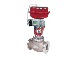
Baker Hughes Proportional Level Controller Pneumatic Set 12840
Need answers fast?
Explore the manual using AI.
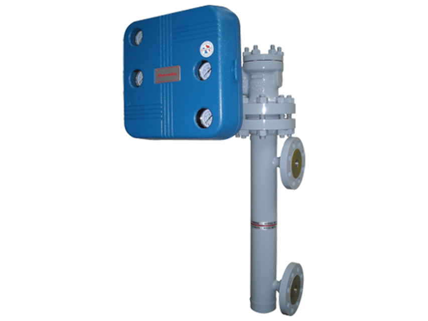
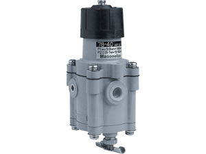
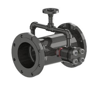
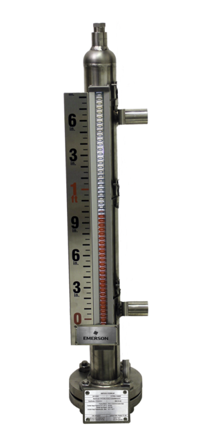
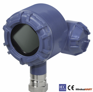
The Baker Hughes Proportional Level Controller Pneumatic Set 12840 is a precision instrument designed for accurate level measurement and control in industrial applications. This robust pneumatic set ensures reliable performance and efficiency, making it essential for maintaining optimal operational conditions in various processes.
Turn manuals into instant answers
with your AI-powered assistantTurn manuals into instant answers
with your AI-powered assistant
Manual for Baker Hughes Proportional Level Controller Pneumatic Set 12840
Complete asset maintenance, one click away
Get instant access to all the maintenance information you need. Empower technicians to perform preventive maintenance with asset packages, ready to use right out of the box.

Documents & Manuals
Find all the essential guides in one place.
 Tensioning Guide
- Belt-diagram
- C-120 pulleys
+ 13 more

Work Order Templates
Pre-built workflows to keep your asset running smoothly.
- Daily Electrical System Inspection
- Replace Roller and Pulley
- Install Engine B-120
+ 29 more

Procedures
Integrate maintenance plans directly into your work orders.
- Motion Industries
- Applied Industrial Technologies
- Electrical Brothers
+ 5 more

Parts
Access the parts list for your equipment in MaintainX.
- Drive Motor
- B2 Rollers
- Tensioning System
+ 40 more
Baker Hughes Proportional Level Controller Pneumatic Set 12840
Create an account to install this asset package.
Maintenance Plans for Baker Hughes Proportional Level Controller Pneumatic Set Model 12840
Integrate maintenance plans directly into your work orders in MaintainX.
Proportional Level Controller Maintenance
Instrument Case Mounting (See Figure 10)
Standard case mounting is left hand; i.e., with Case to left of Displacer. Right hand mounting is optional. To reverse case mounting in the field, proceed as follows: 1. Remove Torque Arm from Protective Housing as outlined in Steps 1 through 3, previous paragraph.
2. Detach Torque Tube Housing Assembly from Protective Housing Assembly by removing stud nuts.
3. Attach Torque Tube Housing Assembly on opposite side of Protective Housing Assembly.
4. Reassemble Torque Arm, Protective Housing Flange, and Top Flange.
5. Disconnect Control Link from Reversing Arc.
6. Loosen Nut securing Reversing Arc. Turn Reversing Arc over and replace Nut. Before tightening Nut, however, be sure Arc is positioned so that tabs line up with slots (arrow on Reversing Arc should point toward Displacer).
7. Connect Control Link for desired control action and specific gravity.
8. Check Control Setting Scale to see that it agrees with control action. If necessary, reverse scale and knob plate.;

Proportional Level Controller Maintenance
Relay (See Figure 10) Metering Orifice
The Metering Orifice for the Nozzle air supply is fitted with a clean-out plunger which forces a small wire through the jewel orifice.
Disassembly: The Metering Orifice can be removed for cleaning while the Relay remains fastened to the Air Manifold. If further disassembly is required, proceed as follows: 1. Unscrew Mounting Screws which hold Relay to Air Manifold. Break joint carefully to avoid damaging the Relay Gasket.
2. Remove Metering Orifice Body and Retainer Screw and drop Relay Plug and Plug Spring from Relay Body. Remove six screws which hold End Plate, Intermediate plate and Diaphragms to Relay Body. Remove Diaphragm Spring from Relay Body and disassemble Diaphragm Block from Intermediate Plate.
3. Clean parts with clean soft cloth. Use solvent if oil and grease are present. Blow out ports in Body, Intermediate Plate, and End Plate with clean dry air.
Assembly: 1. Assemble Diaphragm Block in Intermediate Plate as shown in Figure 10.
2. Replace Diaphragm Spring in Relay Body. Align holes in Diaphragms with those in Intermediate Plate and End Plate and insert screws. Then assemble on Relay Body. The correct alignment of Intermediate Plate and End Plate on Relay Body is simplified by the use of reference marks.
3 .Assemble Relay Plug, Plug Spring, Retainer Screw, and Metering Orifice.
4. Position the Relay Gasket on Air Manifold. After establishing correct position, slip Relay Gasket over the two Mounting Screws on Relay and fasten Relay to Air Manifold.
Proportional Level Controller Maintenance
Resistance Unit (See Figure 11)
On Model 12810 proportional-reset controllers, the Resistance Unit may require occasional cleaning.
Disassembly: 1. Turn Reset Knob counterclockwise and lift Reset Pointer so that it clears stop on the Reset Dial.
2. Unscrew Reset Knob to end of thread and remove.
3. Use wrench on hex of Resistance Unit body and turn counterclockwise to end of thread.
4. Pull Resistance Unit Body from Frame with twisting motion to overcome friction of O-Ring.
5. Unscrew Spring Retainer from Body and remove Spring, Spring Button, Plug, and O-Ring.
6. Blow out ports and wipe parts with clean, lint-free cloth.
Assembly: 1. Reassemble Spring Retainer, Spring, Spring Button, Plug, and O-Ring on Body.
Proportional Level Controller Cleaning
Nozzle
To Clean: Shut off air supply.
Disconnect Nozzle Tubing from Air Manifold. Loosen Set Screw securing Nozzle in Nozzle Bracket and withdraw Nozzle.
Diameter of Nozzle hole is .020 (No. 76 drill). Push drill or wire of smaller diameter through hole. Blow out tubing with clean, dry air.
Replace Nozzle in Nozzle Bracket. Hold Nozzle firmly against shoulder in Nozzle Bracket and tighten Set Screw. Connect tubing to Air Manifold.;
Proportional Level Controller Check
- The following should be checked at regular intervals to obtain maximum performance of the control system
- Filter-Regulator - Accumulation of condensate from the air supply line should be removed by opening the petcock in the bottom of the drip-well.
- Control Valve - Refer to Control Valve instructions.
- Air Circuit - The frequency with which Metering Orifice and Nozzle should be checked will depend on the condition of the air supply.;
Parts for Baker Hughes Proportional Level Controller Pneumatic Set 12840
Access the parts list for your equipment in MaintainX.
Air Manifold S/A
-
Bellows Tubing S/A
-
Case S/A
-
Output Gauge
-
Level Indicating Pointer
-
Air Manifold S/A
-
Bellows Tubing S/A
-
Case S/A
-
Output Gauge
-
Level Indicating Pointer
-
Air Manifold S/A
-
Bellows Tubing S/A
-
Case S/A
-
Output Gauge
-
Level Indicating Pointer
-
Unlock efficiency
with MaintainX CoPilot
MaintainX CoPilot is your expert colleague, on call 24/7, helping your team find the answers they need to keep equipment running.
Reduce Unplanned Downtime
Ensure your team follows consistent procedures to minimize equipment failures and costly delays.
Maximize Asset Availability
Keep your assets running longer and more reliably, with standardized maintenance workflows from OEM manuals.
Lower Maintenance Costs
Turn any technician into an expert to streamline operations, maintain more assets, and reduce overall costs.
Thousands of companies manage their assets with MaintainX

'%3e%3cpath%20fill='url(%23b)'%20d='M66.008%2080.068c-5.084-.786-9.763-3.834-12.442-8.68a16.942%2016.942%200%200%201-1.87-5.18c1.096.19%202.203.476%203.298.87%206.525%202.333%2010.836%207.68%2011.014%2012.99ZM51.47%2061.576c.488-5.524%203.62-10.716%208.847-13.597a17.132%2017.132%200%200%201%2011.335-1.882c-.798%208.145-7.43%2014.848-16.038%2015.599-1.417.119-2.799.07-4.144-.12Zm28.564-11.478a17.513%2017.513%200%200%201%203.727%204.62c4.608%208.335%201.584%2018.813-6.75%2023.409a16.988%2016.988%200%200%201-4.359%201.679%2019.624%2019.624%200%200%201-3.977-12.776c.346-7.561%204.942-13.931%2011.36-16.932Z'/%3e%3cpath%20fill='%23110F0D'%20fill-rule='evenodd'%20d='M142.831%2048.324h4.977V77.03h-4.977V48.324Zm27.278%2013.002c.322%201.048.453%202.263.453%203.62v12.073h-4.787V66.208c0-.75-.047-1.572-.154-2.143-.453-2.382-1.822-3.572-4.215-3.572-2.31%200-3.882%201.274-4.43%203.476-.143.596-.226%201.405-.226%202.25v10.8h-4.787V56.623h4.477v2.989c1.536-2.5%203.906-3.43%206.371-3.43%203.488%200%206.263%201.68%207.298%205.144Zm24.636%207.323c0%203.882-2.358%206.525-5.763%207.727-1.298.453-2.632.643-4.62.643h-10.169V48.324h9.085c1.691%200%203.156.143%204.049.38%203.465.93%205.727%203.68%205.727%207.335%200%202.441-.81%204.156-2.762%205.644%202.905%201.417%204.453%203.727%204.453%206.966Zm-15.634-8.656h4.584c1.024%200%201.917-.143%202.536-.417%201.215-.548%201.905-1.608%201.905-3.167%200-1.548-.643-2.572-1.845-3.132-.691-.31-1.762-.452-2.763-.452h-4.417v7.168Zm10.716%208.465c0-1.536-.893-3.37-3.227-3.893-.428-.095-1.036-.143-1.571-.143h-5.918v8.085h5.501c.56%200%201.429-.048%201.953-.167%201.94-.453%203.262-1.846%203.262-3.882Zm47.747-11.847-8.097%2020.408h-4.429l-8.109-20.408h5.191l5.192%2014.574%205.108-14.574h5.144Zm-20.218%2010.002c0%20.69-.036%201.262-.155%201.94h-15.943c.631%202.87%202.714%204.728%205.882%204.728%202.131%200%203.607-.882%204.703-2.525h4.87c-1.762%204.144-5.204%206.692-9.657%206.692-6.084%200-10.537-4.858-10.537-10.49%200-6.108%204.524-10.776%2010.335-10.776%206.239%200%2010.442%204.954%2010.502%2010.43Zm-4.763-1.405c-.333-2.846-2.643-4.858-5.691-4.858-2.894%200-5.287%201.929-5.621%204.858h11.312Zm-72.667%203.44c0%204.787-3.287%208.371-9.419%208.371H119.363V64.66c-1.917.274-3.87.69-5.811%201.238l4.537%2011.121h-5.418l-3.596-9.585c-5.144%202.084-10.085%205.216-14.217%209.585h-4.786L101.8%2048.312h4.56l5.68%2013.883a44.112%2044.112%200%200%201%207.323-1.774V48.312h9.084c1.703%200%203.156.143%204.061.393%203.453.929%205.727%203.667%205.727%207.323%200%201.917-.738%204.179-2.81%205.691%203.06%201.56%204.501%204.025%204.501%206.93Zm-15.634-8.667a62.664%2062.664%200%200%201%202.06-.036c1.703.012%203.239.131%204.608.37%201.441-.549%202.357-1.727%202.357-3.537%200-1.941-.881-3.144-2.488-3.667-.548-.18-1.358-.286-2.322-.286h-4.215v7.156Zm-16.55%203.905-3.715-9.894-6.394%2016.502c2.833-2.595%206.263-4.858%2010.109-6.608Zm27.254%204.74c0-2.775-3.131-4.347-8.513-4.418-.715%200-1.441.011-2.191.047v8.252h5.918c2.548%200%204.786-1.37%204.786-3.882Z'%20clip-rule='evenodd'/%3e%3c/g%3e%3cdefs%3e%3clinearGradient%20id='b'%20x1='51.47'%20x2='85.916'%20y1='62.946'%20y2='62.946'%20gradientUnits='userSpaceOnUse'%3e%3cstop%20stop-color='%23CD9F28'/%3e%3cstop%20offset='1'%20stop-color='%23ECD80B'/%3e%3c/linearGradient%3e%3cclipPath%20id='a'%3e%3cpath%20fill='%23fff'%20d='M51.47%2045.728h186.104V80.14H51.47z'/%3e%3c/clipPath%3e%3c/defs%3e%3c/svg%3e)


More from Baker Hughes


Explore Other Assets


© 2026 MaintainX. All rights reserved.