


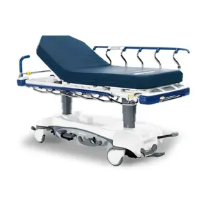
Stryker Stretcher FL19H
Need answers fast?
Explore the manual using AI.
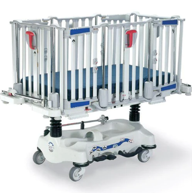
The Stryker Stretcher FL19H is a high-quality medical transport solution designed for patient safety and comfort. This stretcher features advanced hydraulic systems and durable construction, making it ideal for emergency services and healthcare facilities. Regular maintenance ensures optimal performance and longevity of this essential asset.
Turn manuals into instant answers
with your AI-powered assistantTurn manuals into instant answers
with your AI-powered assistant
Manual for Stryker Stretcher FL19H
Complete asset maintenance, one click away
Get instant access to all the maintenance information you need. Empower technicians to perform preventive maintenance with asset packages, ready to use right out of the box.

Documents & Manuals
Find all the essential guides in one place.
 Tensioning Guide
- Belt-diagram
- C-120 pulleys
+ 13 more

Work Order Templates
Pre-built workflows to keep your asset running smoothly.
- Daily Electrical System Inspection
- Replace Roller and Pulley
- Install Engine B-120
+ 29 more

Procedures
Integrate maintenance plans directly into your work orders.
- Motion Industries
- Applied Industrial Technologies
- Electrical Brothers
+ 5 more

Parts
Access the parts list for your equipment in MaintainX.
- Drive Motor
- B2 Rollers
- Tensioning System
+ 40 more
Stryker Stretcher FL19H
Create an account to install this asset package.
Maintenance Plans for Stryker Stretcher Model FL19H
Integrate maintenance plans directly into your work orders in MaintainX.
Lower Plastic Cover Replacement
Rail raised to the highest position and brakes applied
Eight screws removed using a #1 Phillips screwdriver
Lower plastic cover separated without scratching the covers or damaging the upper cover snap pins
Defective lower cover removed
New lower cover installed by reversing the above steps
Proper operation of the rails verified before returning the stretcher to service
Sign off on the lower plastic cover replacement

Litter Removal - Fixed Base Stretcher
Raise the rails to the highest position and apply the brakes
Support both ends of the litter frame using sawhorses (or equivalent)
Using #2 Phillips screwdriver, remove the 18 screws (A) holding the lower cover plates to the litter frame. Remove the cover plates
Lift the black bellows (C) and support them using bungee cords (or equivalent)
Using two 1/2” combination wrenches, remove the four bolts (A) and four locknuts (B) holding the litter support tubes to the two base posts. If the bolts are stuck, raise the end of the litter slightly to ease the removal
With the assistance of another person, lift off the litter and set it aside on a second set of sawhorses
Reverse the above steps to reinstall the litter frame
Verify proper operation of the stretcher before returning it to service
Sign off on the procedure completion
Brake Adjustment Procedure (Hydraulic Base)
Raise the litter and the rails to the highest position.
Lift the base hood, separating the Velcro fasteners holding it to the base, and support it using bungee cords (or equivalent).
Using a 3/4” combination wrench and a 3/4” socket, loosen the jam nut (A).
Using a 3/4” socket, screw in the locknut (B) and test the brakes. Repeat until a proper brake adjustment is found.
Using a 3/4” combination wrench and a 3/4” socket, tighten the jam nut (A).
Remove the bungee cords and replace the base hood.
Sign off on the brake adjustment procedure
Scale System Maintenance
Press and release the Weigh / On button. A weight appears on the scale display four to ten seconds later.
Press and hold the Zero key for at least two seconds. A 0.0 lb/kg weight appears on the display four to ten seconds later.
Press the Weigh / On button to reactivate the scale after it automatically shuts off.
Press the lb / kg key to switch from a weight reading unit to the other.
Press and hold the lb / kg and Memory buttons for at least two seconds to deactivate the lb / kg button.
Place a known weight on the mattress of the stretcher and press the Weigh / On key. Ensure the weight displayed is within the ± 0.5 lb (0.2kg) tolerance.
Press the Weigh / On button and hold the Memory button for at least two seconds to store a weight reading.
Press the Weigh / On button and hold the Memory and Zero buttons for at least two seconds to erase a stored weight.
Press the Weigh / On button and the Change Equipment button to add or remove equipment from the stretcher when the patient is on it.
Endrail Central Column Assembly Replacement
Remove the mattress, raise the rails to the highest position and apply the brakes
Using a #1 Phillips screwdriver, remove the eight screws (A) holding the bottom half of the lower plastic cover (B) to the top half of the lower plastic cover (C)
Insert a small regular screwdriver between the two halves of the lower plastic cover to separate them. Use caution to avoid scratching the covers or damaging the upper cover snap pins
Using a #2 Phillips screwdriver, remove the two screws (D) holding the lower end of the central column to the lower structural member (E)
Using a #1 Phillips screwdriver, remove the eight screws (F) holding the top half of the upper plastic cover (G) to the bottom half of the upper plastic cover (H)
Insert a small regular screwdriver between the two halves of the upper plastic cover to separate them. Use caution to avoid scratching the covers or damaging the lower cover snap pins
Lower the rail to the 14” locking position and place adjustable supports under the rail to support it when the central column is removed
Using a cordless drill and a #2 Phillips bit, remove the 14 screws (J) holding the upper end of the posts and the central column to the upper structural member
Using a 1/2” socket, remove the two bolts and two washers (L) holding the upper end of the two guide posts to the structural member (K)
Parts for Stryker Stretcher FL19H
Access the parts list for your equipment in MaintainX.
Jack, Constant Descent Hydraulic
QDF5060
Caster, 5" Locking (Fixed Height Stretcher)
RT5TF
Access Door Label Set - Red
80-5015
Pump Replacement Assembly
715-100-325
Check Valve
926-20-153
Jack, Constant Descent Hydraulic
QDF5060
Caster, 5" Locking (Fixed Height Stretcher)
RT5TF
Access Door Label Set - Red
80-5015
Pump Replacement Assembly
715-100-325
Check Valve
926-20-153
Jack, Constant Descent Hydraulic
QDF5060
Caster, 5" Locking (Fixed Height Stretcher)
RT5TF
Access Door Label Set - Red
80-5015
Pump Replacement Assembly
715-100-325
Check Valve
926-20-153
Unlock efficiency
with MaintainX CoPilot
MaintainX CoPilot is your expert colleague, on call 24/7, helping your team find the answers they need to keep equipment running.
Reduce Unplanned Downtime
Ensure your team follows consistent procedures to minimize equipment failures and costly delays.
Maximize Asset Availability
Keep your assets running longer and more reliably, with standardized maintenance workflows from OEM manuals.
Lower Maintenance Costs
Turn any technician into an expert to streamline operations, maintain more assets, and reduce overall costs.
Thousands of companies manage their assets with MaintainX

'%3e%3cpath%20fill='url(%23b)'%20d='M66.008%2080.068c-5.084-.786-9.763-3.834-12.442-8.68a16.942%2016.942%200%200%201-1.87-5.18c1.096.19%202.203.476%203.298.87%206.525%202.333%2010.836%207.68%2011.014%2012.99ZM51.47%2061.576c.488-5.524%203.62-10.716%208.847-13.597a17.132%2017.132%200%200%201%2011.335-1.882c-.798%208.145-7.43%2014.848-16.038%2015.599-1.417.119-2.799.07-4.144-.12Zm28.564-11.478a17.513%2017.513%200%200%201%203.727%204.62c4.608%208.335%201.584%2018.813-6.75%2023.409a16.988%2016.988%200%200%201-4.359%201.679%2019.624%2019.624%200%200%201-3.977-12.776c.346-7.561%204.942-13.931%2011.36-16.932Z'/%3e%3cpath%20fill='%23110F0D'%20fill-rule='evenodd'%20d='M142.831%2048.324h4.977V77.03h-4.977V48.324Zm27.278%2013.002c.322%201.048.453%202.263.453%203.62v12.073h-4.787V66.208c0-.75-.047-1.572-.154-2.143-.453-2.382-1.822-3.572-4.215-3.572-2.31%200-3.882%201.274-4.43%203.476-.143.596-.226%201.405-.226%202.25v10.8h-4.787V56.623h4.477v2.989c1.536-2.5%203.906-3.43%206.371-3.43%203.488%200%206.263%201.68%207.298%205.144Zm24.636%207.323c0%203.882-2.358%206.525-5.763%207.727-1.298.453-2.632.643-4.62.643h-10.169V48.324h9.085c1.691%200%203.156.143%204.049.38%203.465.93%205.727%203.68%205.727%207.335%200%202.441-.81%204.156-2.762%205.644%202.905%201.417%204.453%203.727%204.453%206.966Zm-15.634-8.656h4.584c1.024%200%201.917-.143%202.536-.417%201.215-.548%201.905-1.608%201.905-3.167%200-1.548-.643-2.572-1.845-3.132-.691-.31-1.762-.452-2.763-.452h-4.417v7.168Zm10.716%208.465c0-1.536-.893-3.37-3.227-3.893-.428-.095-1.036-.143-1.571-.143h-5.918v8.085h5.501c.56%200%201.429-.048%201.953-.167%201.94-.453%203.262-1.846%203.262-3.882Zm47.747-11.847-8.097%2020.408h-4.429l-8.109-20.408h5.191l5.192%2014.574%205.108-14.574h5.144Zm-20.218%2010.002c0%20.69-.036%201.262-.155%201.94h-15.943c.631%202.87%202.714%204.728%205.882%204.728%202.131%200%203.607-.882%204.703-2.525h4.87c-1.762%204.144-5.204%206.692-9.657%206.692-6.084%200-10.537-4.858-10.537-10.49%200-6.108%204.524-10.776%2010.335-10.776%206.239%200%2010.442%204.954%2010.502%2010.43Zm-4.763-1.405c-.333-2.846-2.643-4.858-5.691-4.858-2.894%200-5.287%201.929-5.621%204.858h11.312Zm-72.667%203.44c0%204.787-3.287%208.371-9.419%208.371H119.363V64.66c-1.917.274-3.87.69-5.811%201.238l4.537%2011.121h-5.418l-3.596-9.585c-5.144%202.084-10.085%205.216-14.217%209.585h-4.786L101.8%2048.312h4.56l5.68%2013.883a44.112%2044.112%200%200%201%207.323-1.774V48.312h9.084c1.703%200%203.156.143%204.061.393%203.453.929%205.727%203.667%205.727%207.323%200%201.917-.738%204.179-2.81%205.691%203.06%201.56%204.501%204.025%204.501%206.93Zm-15.634-8.667a62.664%2062.664%200%200%201%202.06-.036c1.703.012%203.239.131%204.608.37%201.441-.549%202.357-1.727%202.357-3.537%200-1.941-.881-3.144-2.488-3.667-.548-.18-1.358-.286-2.322-.286h-4.215v7.156Zm-16.55%203.905-3.715-9.894-6.394%2016.502c2.833-2.595%206.263-4.858%2010.109-6.608Zm27.254%204.74c0-2.775-3.131-4.347-8.513-4.418-.715%200-1.441.011-2.191.047v8.252h5.918c2.548%200%204.786-1.37%204.786-3.882Z'%20clip-rule='evenodd'/%3e%3c/g%3e%3cdefs%3e%3clinearGradient%20id='b'%20x1='51.47'%20x2='85.916'%20y1='62.946'%20y2='62.946'%20gradientUnits='userSpaceOnUse'%3e%3cstop%20stop-color='%23CD9F28'/%3e%3cstop%20offset='1'%20stop-color='%23ECD80B'/%3e%3c/linearGradient%3e%3cclipPath%20id='a'%3e%3cpath%20fill='%23fff'%20d='M51.47%2045.728h186.104V80.14H51.47z'/%3e%3c/clipPath%3e%3c/defs%3e%3c/svg%3e)


More from Stryker


Explore Other Assets


© 2026 MaintainX. All rights reserved.