


Stryker Stretcher 6516 POWER PRO IT
Need answers fast?
Explore the manual using AI.
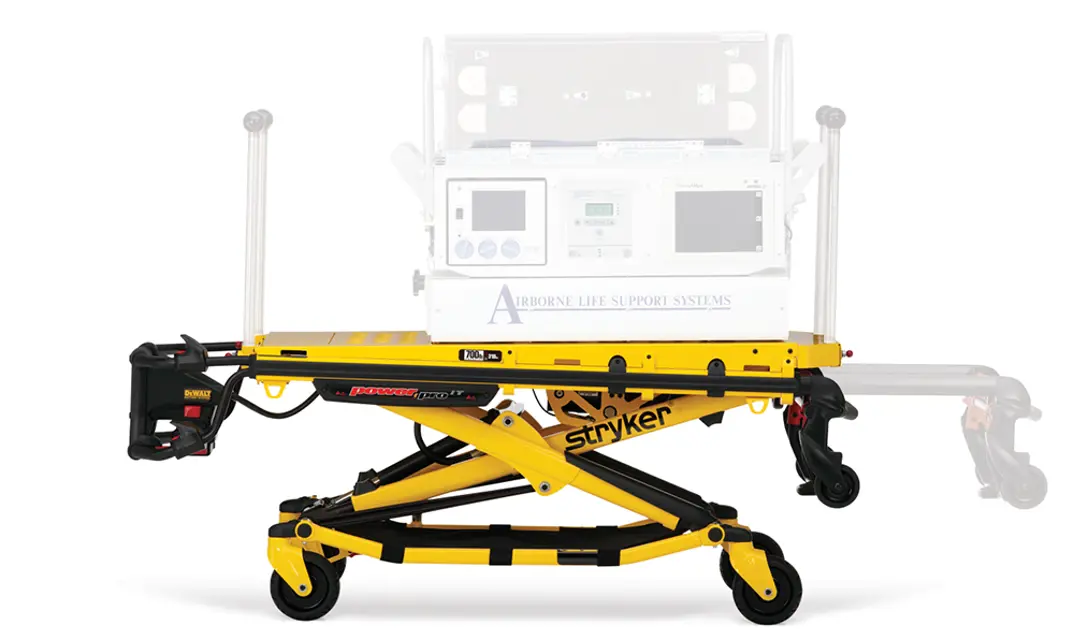
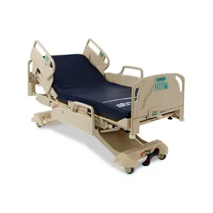
The Stryker Stretcher 6516 POWER PRO IT is a high-performance medical transport solution designed for patient safety and comfort. This stretcher features advanced power capabilities, ensuring efficient mobility and ease of use in emergency situations, making it an essential asset for healthcare providers.
Turn manuals into instant answers
with your AI-powered assistantTurn manuals into instant answers
with your AI-powered assistant
Manual for Stryker Stretcher 6516 POWER PRO IT
Complete asset maintenance, one click away
Get instant access to all the maintenance information you need. Empower technicians to perform preventive maintenance with asset packages, ready to use right out of the box.

Documents & Manuals
Find all the essential guides in one place.
 Tensioning Guide
- Belt-diagram
- C-120 pulleys
+ 13 more

Work Order Templates
Pre-built workflows to keep your asset running smoothly.
- Daily Electrical System Inspection
- Replace Roller and Pulley
- Install Engine B-120
+ 29 more

Procedures
Integrate maintenance plans directly into your work orders.
- Motion Industries
- Applied Industrial Technologies
- Electrical Brothers
+ 5 more

Parts
Access the parts list for your equipment in MaintainX.
- Drive Motor
- B2 Rollers
- Tensioning System
+ 40 more
Stryker Stretcher 6516 POWER PRO IT
Create an account to install this asset package.
Maintenance Plans for Stryker Stretcher Model 6516 POWER PRO IT
Integrate maintenance plans directly into your work orders in MaintainX.
Operating The Retractable Head Section
To extend the head section:
Grasp the outer rail with one hand for support and pull the handle (A), rotating the handle toward the head end of the cot to release the head section from the locked position.
While holding the handle (A) in the released position, pull the head section away from the litter frame, lengthening the head section until it engages in the fully extended position.
Release handle (A) to lock the head section in the extended position.
To retract the head section:
Grasp the outer rail with one hand for support and release the handle (A), rotate the handle toward the head end of the cot to release the head section from the locked position.
While holding the handle (A) in the released position, push the head section toward the litter frame, retracting the head section until it engages in the retracted position.
Release handle (A) to lock the head section in the retracted position.
Sign off on the operation of the retractable head section

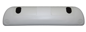
The Air Sled Maintenance
Straps attached to secure the Air Sled to the litter surface
Straps secured from the litter and not the push bars to the Air Sled
Air Sled secured to the cot as shown in Figure 44
Sign off on the Air Sled Maintenance
Manual Release Cable Adjustment
Support the litter so no weight is on the base.
Ensure that the manual release cable is intact
Using a 10 mm combination wrench, loosen the cable lock nut.
Using a 8 mm combination wrench, adjust the tension on the manual release cable so it just starts to touch the manual release dual pull bracket.
Tighten the cable lock nut.
Test for proper adjustment by following steps A-D:
A. Place 50 lb of weight on the hydraulic skin.
B. Load height must read 34-1/2” to 35-1/2”.
C. Place 100 lb of weight on the hydraulic skin, raise cot to full height, pull the manual release handle and ensure that the cot does not drop.
Headsection Replacement
Raise the cot to the full upright position.
Using a 7/16” combination wrench and a 3/16” hex wrench, remove the two screws (A) that secure the cap bearings to the base litter interface bracket (one on each side) (Figure 47).
Squeeze the head release handles and slowly remove the head section assembly.
Reverse steps to reinstall.
Verify proper operation of the unit before returning it to service.
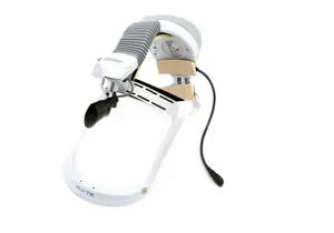
The Airbornetm Stackable Replacement
Warning: This procedure requires trained personnel with PPE!
Using the 1/2” socket and ratchet, remove the four 5/16” hex nuts and washers (A) from the mounting studs (B) on the adaptor as shown in Figure 41.
Locate the mounting holes in the bottom of the oxygen bottle module (C).
Install the oxygen bottle holder on the adaptor mounting studs (B) with the bottle openings facing toward the retractable head section. Verify that all four mounting studs are properly seated into the mounting holes of the oxygen bottle holder.
Using a 1/2” socket and ratchet, install the four 5/16” hex nuts and washers (A) that were removed in step one and securely tighten them.
Sign off on the adaptor installation
Parts for Stryker Stretcher 6516 POWER PRO IT
Access the parts list for your equipment in MaintainX.
Button Head Cap Screw
0004-589-000
Outer Rail Bumper
6500-001-127
Rivet
0025-079-000
Crest-To-Crest Spring
0038-574-000
Label, Power-PRO™ IT
6510-001-116
Button Head Cap Screw
0004-589-000
Outer Rail Bumper
6500-001-127
Rivet
0025-079-000
Crest-To-Crest Spring
0038-574-000
Label, Power-PRO™ IT
6510-001-116
Button Head Cap Screw
0004-589-000
Outer Rail Bumper
6500-001-127
Rivet
0025-079-000
Crest-To-Crest Spring
0038-574-000
Label, Power-PRO™ IT
6510-001-116
Unlock efficiency
with MaintainX CoPilot
MaintainX CoPilot is your expert colleague, on call 24/7, helping your team find the answers they need to keep equipment running.
Reduce Unplanned Downtime
Ensure your team follows consistent procedures to minimize equipment failures and costly delays.
Maximize Asset Availability
Keep your assets running longer and more reliably, with standardized maintenance workflows from OEM manuals.
Lower Maintenance Costs
Turn any technician into an expert to streamline operations, maintain more assets, and reduce overall costs.
Thousands of companies manage their assets with MaintainX

'%3e%3cpath%20fill='url(%23b)'%20d='M66.008%2080.068c-5.084-.786-9.763-3.834-12.442-8.68a16.942%2016.942%200%200%201-1.87-5.18c1.096.19%202.203.476%203.298.87%206.525%202.333%2010.836%207.68%2011.014%2012.99ZM51.47%2061.576c.488-5.524%203.62-10.716%208.847-13.597a17.132%2017.132%200%200%201%2011.335-1.882c-.798%208.145-7.43%2014.848-16.038%2015.599-1.417.119-2.799.07-4.144-.12Zm28.564-11.478a17.513%2017.513%200%200%201%203.727%204.62c4.608%208.335%201.584%2018.813-6.75%2023.409a16.988%2016.988%200%200%201-4.359%201.679%2019.624%2019.624%200%200%201-3.977-12.776c.346-7.561%204.942-13.931%2011.36-16.932Z'/%3e%3cpath%20fill='%23110F0D'%20fill-rule='evenodd'%20d='M142.831%2048.324h4.977V77.03h-4.977V48.324Zm27.278%2013.002c.322%201.048.453%202.263.453%203.62v12.073h-4.787V66.208c0-.75-.047-1.572-.154-2.143-.453-2.382-1.822-3.572-4.215-3.572-2.31%200-3.882%201.274-4.43%203.476-.143.596-.226%201.405-.226%202.25v10.8h-4.787V56.623h4.477v2.989c1.536-2.5%203.906-3.43%206.371-3.43%203.488%200%206.263%201.68%207.298%205.144Zm24.636%207.323c0%203.882-2.358%206.525-5.763%207.727-1.298.453-2.632.643-4.62.643h-10.169V48.324h9.085c1.691%200%203.156.143%204.049.38%203.465.93%205.727%203.68%205.727%207.335%200%202.441-.81%204.156-2.762%205.644%202.905%201.417%204.453%203.727%204.453%206.966Zm-15.634-8.656h4.584c1.024%200%201.917-.143%202.536-.417%201.215-.548%201.905-1.608%201.905-3.167%200-1.548-.643-2.572-1.845-3.132-.691-.31-1.762-.452-2.763-.452h-4.417v7.168Zm10.716%208.465c0-1.536-.893-3.37-3.227-3.893-.428-.095-1.036-.143-1.571-.143h-5.918v8.085h5.501c.56%200%201.429-.048%201.953-.167%201.94-.453%203.262-1.846%203.262-3.882Zm47.747-11.847-8.097%2020.408h-4.429l-8.109-20.408h5.191l5.192%2014.574%205.108-14.574h5.144Zm-20.218%2010.002c0%20.69-.036%201.262-.155%201.94h-15.943c.631%202.87%202.714%204.728%205.882%204.728%202.131%200%203.607-.882%204.703-2.525h4.87c-1.762%204.144-5.204%206.692-9.657%206.692-6.084%200-10.537-4.858-10.537-10.49%200-6.108%204.524-10.776%2010.335-10.776%206.239%200%2010.442%204.954%2010.502%2010.43Zm-4.763-1.405c-.333-2.846-2.643-4.858-5.691-4.858-2.894%200-5.287%201.929-5.621%204.858h11.312Zm-72.667%203.44c0%204.787-3.287%208.371-9.419%208.371H119.363V64.66c-1.917.274-3.87.69-5.811%201.238l4.537%2011.121h-5.418l-3.596-9.585c-5.144%202.084-10.085%205.216-14.217%209.585h-4.786L101.8%2048.312h4.56l5.68%2013.883a44.112%2044.112%200%200%201%207.323-1.774V48.312h9.084c1.703%200%203.156.143%204.061.393%203.453.929%205.727%203.667%205.727%207.323%200%201.917-.738%204.179-2.81%205.691%203.06%201.56%204.501%204.025%204.501%206.93Zm-15.634-8.667a62.664%2062.664%200%200%201%202.06-.036c1.703.012%203.239.131%204.608.37%201.441-.549%202.357-1.727%202.357-3.537%200-1.941-.881-3.144-2.488-3.667-.548-.18-1.358-.286-2.322-.286h-4.215v7.156Zm-16.55%203.905-3.715-9.894-6.394%2016.502c2.833-2.595%206.263-4.858%2010.109-6.608Zm27.254%204.74c0-2.775-3.131-4.347-8.513-4.418-.715%200-1.441.011-2.191.047v8.252h5.918c2.548%200%204.786-1.37%204.786-3.882Z'%20clip-rule='evenodd'/%3e%3c/g%3e%3cdefs%3e%3clinearGradient%20id='b'%20x1='51.47'%20x2='85.916'%20y1='62.946'%20y2='62.946'%20gradientUnits='userSpaceOnUse'%3e%3cstop%20stop-color='%23CD9F28'/%3e%3cstop%20offset='1'%20stop-color='%23ECD80B'/%3e%3c/linearGradient%3e%3cclipPath%20id='a'%3e%3cpath%20fill='%23fff'%20d='M51.47%2045.728h186.104V80.14H51.47z'/%3e%3c/clipPath%3e%3c/defs%3e%3c/svg%3e)


More from Stryker


Explore Other Assets


© 2026 MaintainX. All rights reserved.