


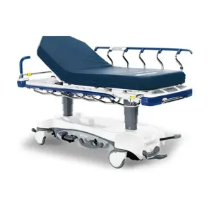
Stryker Stretcher 2141
Need answers fast?
Explore the manual using AI.
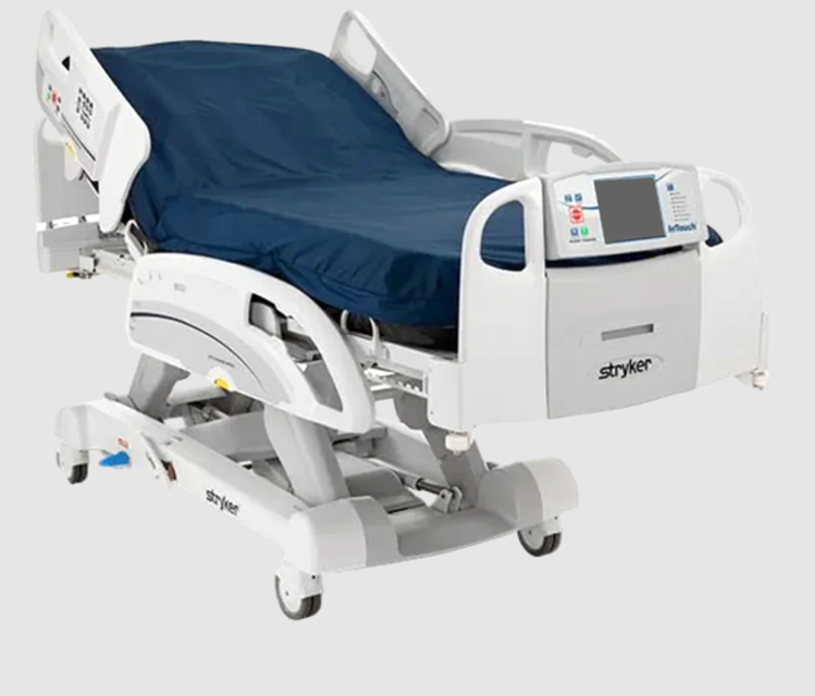
The Stryker Stretcher 2141 is a reliable and versatile medical transport solution designed for patient safety and comfort. This stretcher features advanced hydraulic systems and durable construction, making it ideal for emergency and hospital environments. Ensure optimal performance with regular maintenance and quality spare parts.
Turn manuals into instant answers
with your AI-powered assistantTurn manuals into instant answers
with your AI-powered assistant
Manual for Stryker Stretcher 2141
Complete asset maintenance, one click away
Get instant access to all the maintenance information you need. Empower technicians to perform preventive maintenance with asset packages, ready to use right out of the box.

Documents & Manuals
Find all the essential guides in one place.
 Tensioning Guide
- Belt-diagram
- C-120 pulleys
+ 13 more

Work Order Templates
Pre-built workflows to keep your asset running smoothly.
- Daily Electrical System Inspection
- Replace Roller and Pulley
- Install Engine B-120
+ 29 more

Procedures
Integrate maintenance plans directly into your work orders.
- Motion Industries
- Applied Industrial Technologies
- Electrical Brothers
+ 5 more

Parts
Access the parts list for your equipment in MaintainX.
- Drive Motor
- B2 Rollers
- Tensioning System
+ 40 more
Stryker Stretcher 2141
Create an account to install this asset package.
Maintenance Plans for Stryker Stretcher Model 2141
Integrate maintenance plans directly into your work orders in MaintainX.
Gatch Angle Sensor Replacement
Plug bed into wall outlet
Set the brakes using one of the brake control locations or by using the manual brake pedal
Raise the bed to the full up position
If gatch motor will run, raise gatch up to approximately 20 degrees. If the gatch motor will not run, then put the bed into the calibration mode step one as shown on page 21
Working from the bottom left side of the litter, under the gatch section, use a stubby Phillips screwdriver and remove the two screws securing the gatch angle sensor to the bottom of the gatch frame
Using an ESD system, properly ground yourself
Unclip the three clips holding the board cover on
Unplug the cable from the board
Reverse the steps to install new gatch angle sensor

Foot Actuator Replacement
Bed plugged into wall outlet
Brakes set using one of the brake control locations or the manual brake pedal
Mattress removed and set aside
Foot section supported with a jack stand by lowering the bed height
Zip ties securing the actuator cable to the bed cut using diagonal pliers
Mattress assembly removed or folded back to expose the foot section
Two screws securing the electrical cover from the foot section removed using a Phillips screwdriver
Actuator unplugged from J1 and cable fed down to actuator
Two rue clips from the clevis pins holding the actuator in place removed using needle-nose pliers
Gatch Actuator Replacement
Plug bed into wall outlet
Set the brakes using one of the brake control locations or by using the manual brake pedal
Remove the mattress and set aside
Raise bed to the full up position
Lower the gatch down to take the tension off of the actuator mounting pins
Unplug the actuator cable from the quick connect near the actuator
Using Needle-nose pliers, remove the two rue clips from the clevis pins holding the actuator in place
Holding the actuator with one hand, remove the clevis pins securing the actuator to the bed then remove the actuator
Reverse these steps to reinstall
Brake / Neutral / Drive Potentiometer Replacement
Plug bed into wall outlet
Raise the bed lift and patient’s left siderails all the way up
Remove the base center covers (foot, center, and head)
Remove the patient’s left base frame cover
Cut the two wire ties securing the potentiometer to the potentiometer bracket; then cut the two wire ties securing the potentiometer wires to the frame
Remove the electrical tape holding the quick connection together
Reverse the above procedures for installation of the new potentiometer
Recalibrate the bed (refer to Bed Calibration procedures on page 21)
Test all bed functionality prior to putting the bed back into service
Bed Lift Actuator (Foot) Replacement - (Base)
Plug bed into wall outlet
Raise head end siderails to full up position and ensure brakes are activated
Remove head end base cover by pulling up and out
Remove center base cover by pulling up and out
Using diagonal pliers, cut the zip tie securing the actuator cable to the base frame
Using Needle-nose pliers, remove the rue clips from the clevis pins securing the actuator
Lower the bed all of the way down so the litter is supported by the base litter stops
Using the bed up/down controls, tap the up or down button to remove tension on the clevis pins and remove clevis pins
Unplug the cable quick connect and remove the actuator
Parts for Stryker Stretcher 2141
Access the parts list for your equipment in MaintainX.
Actuator
QDF27-1215
Actuator
QDF27-1214
Actuator
QDF27-1227
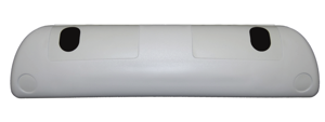
InTouch 3.0 Footboard Assembly with iBed
27-2761K
Angle Sensor
27-2477
Actuator
QDF27-1215
Actuator
QDF27-1214
Actuator
QDF27-1227
InTouch 3.0 Footboard Assembly with iBed
27-2761K
Angle Sensor
27-2477
Actuator
QDF27-1215
Actuator
QDF27-1214
Actuator
QDF27-1227
InTouch 3.0 Footboard Assembly with iBed
27-2761K
Angle Sensor
27-2477
Unlock efficiency
with MaintainX CoPilot
MaintainX CoPilot is your expert colleague, on call 24/7, helping your team find the answers they need to keep equipment running.
Reduce Unplanned Downtime
Ensure your team follows consistent procedures to minimize equipment failures and costly delays.
Maximize Asset Availability
Keep your assets running longer and more reliably, with standardized maintenance workflows from OEM manuals.
Lower Maintenance Costs
Turn any technician into an expert to streamline operations, maintain more assets, and reduce overall costs.
Thousands of companies manage their assets with MaintainX

'%3e%3cpath%20fill='url(%23b)'%20d='M66.008%2080.068c-5.084-.786-9.763-3.834-12.442-8.68a16.942%2016.942%200%200%201-1.87-5.18c1.096.19%202.203.476%203.298.87%206.525%202.333%2010.836%207.68%2011.014%2012.99ZM51.47%2061.576c.488-5.524%203.62-10.716%208.847-13.597a17.132%2017.132%200%200%201%2011.335-1.882c-.798%208.145-7.43%2014.848-16.038%2015.599-1.417.119-2.799.07-4.144-.12Zm28.564-11.478a17.513%2017.513%200%200%201%203.727%204.62c4.608%208.335%201.584%2018.813-6.75%2023.409a16.988%2016.988%200%200%201-4.359%201.679%2019.624%2019.624%200%200%201-3.977-12.776c.346-7.561%204.942-13.931%2011.36-16.932Z'/%3e%3cpath%20fill='%23110F0D'%20fill-rule='evenodd'%20d='M142.831%2048.324h4.977V77.03h-4.977V48.324Zm27.278%2013.002c.322%201.048.453%202.263.453%203.62v12.073h-4.787V66.208c0-.75-.047-1.572-.154-2.143-.453-2.382-1.822-3.572-4.215-3.572-2.31%200-3.882%201.274-4.43%203.476-.143.596-.226%201.405-.226%202.25v10.8h-4.787V56.623h4.477v2.989c1.536-2.5%203.906-3.43%206.371-3.43%203.488%200%206.263%201.68%207.298%205.144Zm24.636%207.323c0%203.882-2.358%206.525-5.763%207.727-1.298.453-2.632.643-4.62.643h-10.169V48.324h9.085c1.691%200%203.156.143%204.049.38%203.465.93%205.727%203.68%205.727%207.335%200%202.441-.81%204.156-2.762%205.644%202.905%201.417%204.453%203.727%204.453%206.966Zm-15.634-8.656h4.584c1.024%200%201.917-.143%202.536-.417%201.215-.548%201.905-1.608%201.905-3.167%200-1.548-.643-2.572-1.845-3.132-.691-.31-1.762-.452-2.763-.452h-4.417v7.168Zm10.716%208.465c0-1.536-.893-3.37-3.227-3.893-.428-.095-1.036-.143-1.571-.143h-5.918v8.085h5.501c.56%200%201.429-.048%201.953-.167%201.94-.453%203.262-1.846%203.262-3.882Zm47.747-11.847-8.097%2020.408h-4.429l-8.109-20.408h5.191l5.192%2014.574%205.108-14.574h5.144Zm-20.218%2010.002c0%20.69-.036%201.262-.155%201.94h-15.943c.631%202.87%202.714%204.728%205.882%204.728%202.131%200%203.607-.882%204.703-2.525h4.87c-1.762%204.144-5.204%206.692-9.657%206.692-6.084%200-10.537-4.858-10.537-10.49%200-6.108%204.524-10.776%2010.335-10.776%206.239%200%2010.442%204.954%2010.502%2010.43Zm-4.763-1.405c-.333-2.846-2.643-4.858-5.691-4.858-2.894%200-5.287%201.929-5.621%204.858h11.312Zm-72.667%203.44c0%204.787-3.287%208.371-9.419%208.371H119.363V64.66c-1.917.274-3.87.69-5.811%201.238l4.537%2011.121h-5.418l-3.596-9.585c-5.144%202.084-10.085%205.216-14.217%209.585h-4.786L101.8%2048.312h4.56l5.68%2013.883a44.112%2044.112%200%200%201%207.323-1.774V48.312h9.084c1.703%200%203.156.143%204.061.393%203.453.929%205.727%203.667%205.727%207.323%200%201.917-.738%204.179-2.81%205.691%203.06%201.56%204.501%204.025%204.501%206.93Zm-15.634-8.667a62.664%2062.664%200%200%201%202.06-.036c1.703.012%203.239.131%204.608.37%201.441-.549%202.357-1.727%202.357-3.537%200-1.941-.881-3.144-2.488-3.667-.548-.18-1.358-.286-2.322-.286h-4.215v7.156Zm-16.55%203.905-3.715-9.894-6.394%2016.502c2.833-2.595%206.263-4.858%2010.109-6.608Zm27.254%204.74c0-2.775-3.131-4.347-8.513-4.418-.715%200-1.441.011-2.191.047v8.252h5.918c2.548%200%204.786-1.37%204.786-3.882Z'%20clip-rule='evenodd'/%3e%3c/g%3e%3cdefs%3e%3clinearGradient%20id='b'%20x1='51.47'%20x2='85.916'%20y1='62.946'%20y2='62.946'%20gradientUnits='userSpaceOnUse'%3e%3cstop%20stop-color='%23CD9F28'/%3e%3cstop%20offset='1'%20stop-color='%23ECD80B'/%3e%3c/linearGradient%3e%3cclipPath%20id='a'%3e%3cpath%20fill='%23fff'%20d='M51.47%2045.728h186.104V80.14H51.47z'/%3e%3c/clipPath%3e%3c/defs%3e%3c/svg%3e)


More from Stryker


Explore Other Assets


© 2026 MaintainX. All rights reserved.