


Stryker Stretcher 1731
Need answers fast?
Explore the manual using AI.
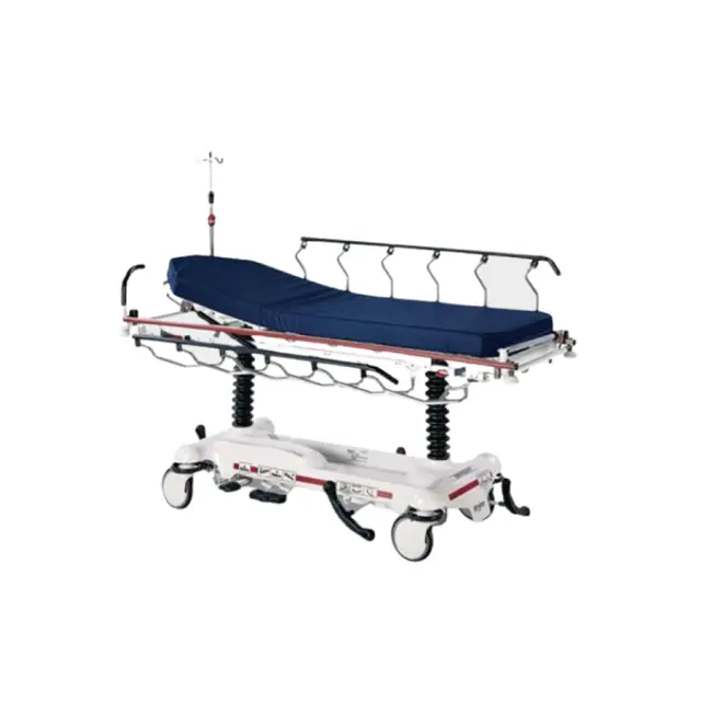
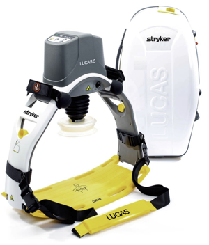
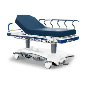
The Stryker Stretcher 1731 is a reliable and versatile medical transport solution designed for patient safety and comfort. This stretcher features advanced hydraulic systems and durable construction, making it ideal for emergency medical services and hospital use. Experience enhanced mobility and efficiency with the Stryker Stretcher 1731.
Turn manuals into instant answers
with your AI-powered assistantTurn manuals into instant answers
with your AI-powered assistant
Manual for Stryker Stretcher 1731
Complete asset maintenance, one click away
Get instant access to all the maintenance information you need. Empower technicians to perform preventive maintenance with asset packages, ready to use right out of the box.

Documents & Manuals
Find all the essential guides in one place.
 Tensioning Guide
- Belt-diagram
- C-120 pulleys
+ 13 more

Work Order Templates
Pre-built workflows to keep your asset running smoothly.
- Daily Electrical System Inspection
- Replace Roller and Pulley
- Install Engine B-120
+ 29 more

Procedures
Integrate maintenance plans directly into your work orders.
- Motion Industries
- Applied Industrial Technologies
- Electrical Brothers
+ 5 more

Parts
Access the parts list for your equipment in MaintainX.
- Drive Motor
- B2 Rollers
- Tensioning System
+ 40 more
Stryker Stretcher 1731
Create an account to install this asset package.
Maintenance Plans for Stryker Stretcher Model 1731
Integrate maintenance plans directly into your work orders in MaintainX.
Release Pedal Adjustment
Warning: Ensure the machine is powered off before starting the procedure.
Manually disengage the release pedal swivel (item K on page 33) from the release pedal assembly.
To increase the release rod engagement with the release valve, turn the release pedal swivel clockwise on the threaded release rod.
To decrease the release rod engagement with the release valve, turn the release pedal swivel counterclockwise on the threaded release rod.
Sign off on the release pedal adjustment

Pneumatic Fowler Adjustment
Refer to drawings 1211−31−10 & 1211−31−20 for parts reference
Move Fowler to this position for easier access
Set screws removed using a 3/32” hex Allen wrench?
Cap screws, flat washers and hex nuts removed using a 9/16” box end wrench and 5/16” hex Allen wrench?
Adjustment of the Fowler
Cap screw replaced and Fowler tested for position holding?
Washers and hex nuts replaced to secure the pivot bolts?
Set screws reinstalled using thread locktite?
Foot End Hydraulic Jack Replacement (Base With Dual Controls)
Remove the litter top from the stretcher
Lift the base hood off the base frame
Remove the two hex washer head screws and washers connecting the pump pedal link to the foot end pump pedal assembly and pump connecting rod
Remove the foot end release rod from the release valve on the jack assembly by dislodging the release pedal swivel from the pins on the release pedal weldment
Dislodge the jack pump piston from the pump connecting rod
Remove the two hex washer head screws holding the reservoir clamp
Remove the jack assembly
Reverse steps 1−7 to install the new jack
Sign off on the hydraulic jack replacement
Head End Hydraulic Jack Replacement
Remove the litter top from the stretcher
Remove the two hex head screws holding the jack base to the stretcher base frame
Remove the two hex head screws holding the jack reservoir clamp to the base frame and remove the clamps
Lift straight up on the pump connecting rod and disconnect the pump piston from the connecting rod
Disconnect the pump pedal swivel from the release pedal mounting plate
Remove the head end release rod from the release valve assembly
Remove the two hex head screws holding the jack base to the stretcher base frame
Lift out the jack assembly
Install the bolts on the jack and reservoir clamp but do not tighten them fully
Fifth Wheel Assembly Replacement
Using a 1/2” socket and 3/8” drive ratchet
Remove the 1/2” bolt holding the fifth wheel cam drive link and fifth wheel drive link to the fifth wheel cam
Remove the two 1/2” bolts holding the fifth wheel mounting bracket to the base frame weldment
Remove the fifth wheel assembly
Reverse steps 1 and 2 to reinstall the fifth wheel
Reinstall the fifth wheel cam drive link and fifth wheel drive link to the fifth wheel cam
Reinstall the fifth wheel mounting bracket to the base frame weldment
Sign off on the fifth wheel assembly replacement
Parts for Stryker Stretcher 1731
Access the parts list for your equipment in MaintainX.
Head Board/Push Bar
1711-139-010
Wheel Cover Replacement Kit
1010-056-200
Paint, Touch-Up, Gray, Spray Can
7000-001-317
Nylock Hex Nut
0016-035-000
Foot Board/Chartholder
0926-040-000
Head Board/Push Bar
1711-139-010
Wheel Cover Replacement Kit
1010-056-200
Paint, Touch-Up, Gray, Spray Can
7000-001-317
Nylock Hex Nut
0016-035-000
Foot Board/Chartholder
0926-040-000
Head Board/Push Bar
1711-139-010
Wheel Cover Replacement Kit
1010-056-200
Paint, Touch-Up, Gray, Spray Can
7000-001-317
Nylock Hex Nut
0016-035-000
Foot Board/Chartholder
0926-040-000
Unlock efficiency
with MaintainX CoPilot
MaintainX CoPilot is your expert colleague, on call 24/7, helping your team find the answers they need to keep equipment running.
Reduce Unplanned Downtime
Ensure your team follows consistent procedures to minimize equipment failures and costly delays.
Maximize Asset Availability
Keep your assets running longer and more reliably, with standardized maintenance workflows from OEM manuals.
Lower Maintenance Costs
Turn any technician into an expert to streamline operations, maintain more assets, and reduce overall costs.
Thousands of companies manage their assets with MaintainX

'%3e%3cpath%20fill='url(%23b)'%20d='M66.008%2080.068c-5.084-.786-9.763-3.834-12.442-8.68a16.942%2016.942%200%200%201-1.87-5.18c1.096.19%202.203.476%203.298.87%206.525%202.333%2010.836%207.68%2011.014%2012.99ZM51.47%2061.576c.488-5.524%203.62-10.716%208.847-13.597a17.132%2017.132%200%200%201%2011.335-1.882c-.798%208.145-7.43%2014.848-16.038%2015.599-1.417.119-2.799.07-4.144-.12Zm28.564-11.478a17.513%2017.513%200%200%201%203.727%204.62c4.608%208.335%201.584%2018.813-6.75%2023.409a16.988%2016.988%200%200%201-4.359%201.679%2019.624%2019.624%200%200%201-3.977-12.776c.346-7.561%204.942-13.931%2011.36-16.932Z'/%3e%3cpath%20fill='%23110F0D'%20fill-rule='evenodd'%20d='M142.831%2048.324h4.977V77.03h-4.977V48.324Zm27.278%2013.002c.322%201.048.453%202.263.453%203.62v12.073h-4.787V66.208c0-.75-.047-1.572-.154-2.143-.453-2.382-1.822-3.572-4.215-3.572-2.31%200-3.882%201.274-4.43%203.476-.143.596-.226%201.405-.226%202.25v10.8h-4.787V56.623h4.477v2.989c1.536-2.5%203.906-3.43%206.371-3.43%203.488%200%206.263%201.68%207.298%205.144Zm24.636%207.323c0%203.882-2.358%206.525-5.763%207.727-1.298.453-2.632.643-4.62.643h-10.169V48.324h9.085c1.691%200%203.156.143%204.049.38%203.465.93%205.727%203.68%205.727%207.335%200%202.441-.81%204.156-2.762%205.644%202.905%201.417%204.453%203.727%204.453%206.966Zm-15.634-8.656h4.584c1.024%200%201.917-.143%202.536-.417%201.215-.548%201.905-1.608%201.905-3.167%200-1.548-.643-2.572-1.845-3.132-.691-.31-1.762-.452-2.763-.452h-4.417v7.168Zm10.716%208.465c0-1.536-.893-3.37-3.227-3.893-.428-.095-1.036-.143-1.571-.143h-5.918v8.085h5.501c.56%200%201.429-.048%201.953-.167%201.94-.453%203.262-1.846%203.262-3.882Zm47.747-11.847-8.097%2020.408h-4.429l-8.109-20.408h5.191l5.192%2014.574%205.108-14.574h5.144Zm-20.218%2010.002c0%20.69-.036%201.262-.155%201.94h-15.943c.631%202.87%202.714%204.728%205.882%204.728%202.131%200%203.607-.882%204.703-2.525h4.87c-1.762%204.144-5.204%206.692-9.657%206.692-6.084%200-10.537-4.858-10.537-10.49%200-6.108%204.524-10.776%2010.335-10.776%206.239%200%2010.442%204.954%2010.502%2010.43Zm-4.763-1.405c-.333-2.846-2.643-4.858-5.691-4.858-2.894%200-5.287%201.929-5.621%204.858h11.312Zm-72.667%203.44c0%204.787-3.287%208.371-9.419%208.371H119.363V64.66c-1.917.274-3.87.69-5.811%201.238l4.537%2011.121h-5.418l-3.596-9.585c-5.144%202.084-10.085%205.216-14.217%209.585h-4.786L101.8%2048.312h4.56l5.68%2013.883a44.112%2044.112%200%200%201%207.323-1.774V48.312h9.084c1.703%200%203.156.143%204.061.393%203.453.929%205.727%203.667%205.727%207.323%200%201.917-.738%204.179-2.81%205.691%203.06%201.56%204.501%204.025%204.501%206.93Zm-15.634-8.667a62.664%2062.664%200%200%201%202.06-.036c1.703.012%203.239.131%204.608.37%201.441-.549%202.357-1.727%202.357-3.537%200-1.941-.881-3.144-2.488-3.667-.548-.18-1.358-.286-2.322-.286h-4.215v7.156Zm-16.55%203.905-3.715-9.894-6.394%2016.502c2.833-2.595%206.263-4.858%2010.109-6.608Zm27.254%204.74c0-2.775-3.131-4.347-8.513-4.418-.715%200-1.441.011-2.191.047v8.252h5.918c2.548%200%204.786-1.37%204.786-3.882Z'%20clip-rule='evenodd'/%3e%3c/g%3e%3cdefs%3e%3clinearGradient%20id='b'%20x1='51.47'%20x2='85.916'%20y1='62.946'%20y2='62.946'%20gradientUnits='userSpaceOnUse'%3e%3cstop%20stop-color='%23CD9F28'/%3e%3cstop%20offset='1'%20stop-color='%23ECD80B'/%3e%3c/linearGradient%3e%3cclipPath%20id='a'%3e%3cpath%20fill='%23fff'%20d='M51.47%2045.728h186.104V80.14H51.47z'/%3e%3c/clipPath%3e%3c/defs%3e%3c/svg%3e)


More from Stryker


Explore Other Assets


© 2026 MaintainX. All rights reserved.