


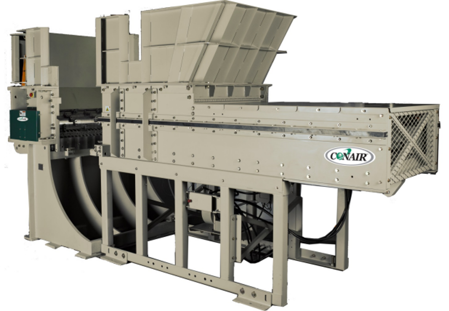
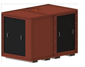
The Piovan Group Shredder SHX is a robust industrial asset designed for efficient material processing. This shredder model excels in waste reduction and recycling applications, ensuring optimal performance and reliability in demanding environments. Regular maintenance is essential to maximize its lifespan and operational efficiency.
Turn manuals into instant answers
with your AI-powered assistantTurn manuals into instant answers
with your AI-powered assistant
Complete asset maintenance, one click away
Get instant access to all the maintenance information you need. Empower technicians to perform preventive maintenance with asset packages, ready to use right out of the box.

Documents & Manuals
Find all the essential guides in one place.
 Tensioning Guide
- Belt-diagram
- C-120 pulleys
+ 13 more

Work Order Templates
Pre-built workflows to keep your asset running smoothly.
- Daily Electrical System Inspection
- Replace Roller and Pulley
- Install Engine B-120
+ 29 more

Procedures
Integrate maintenance plans directly into your work orders.
- Motion Industries
- Applied Industrial Technologies
- Electrical Brothers
+ 5 more

Parts
Access the parts list for your equipment in MaintainX.
- Drive Motor
- B2 Rollers
- Tensioning System
+ 40 more
Piovan Group Shredder SHX
Create an account to install this asset package.
Maintenance Plans for Piovan Group Shredder Model SHX
Integrate maintenance plans directly into your work orders in MaintainX.
1 Monthly Inspection
- Inspect Visually Torque Arm
- Inspect bushing for fatigue cracks in rubber cushion area. Inspect bushing pin bore for excessive movement between diameter and bore of bushing. The bushings are pressed into the torque arm assembly; therefore it is recommended to replace torque arm assembly and adjusting pin if bushing replacement is necessary
- Inspect Ram Wipers. Replacement will be necessary when 5/8" to 3/4" of wear is present (page 47)
- Inspect for wear on monthly basis. They are generally considered worn when approximately 1/8” from original specs and should be replaced (page 48)
- The hydraulics power system employs a high quality return oil filter (page 49). The filter has an indicator that changes color when it is time to be changed. Check filter every 30 days. The hydraulic fluid should last indefinitely unless it suffers severe overheating
- Inspect breather filter and replace when required. If machine is operated in extreme temperature conditions, adding an oil heater or oil cooler may be required
- The oil level in the tank should be checked on a regular basis. Refill hydraulic oil as necessary with this oil or equivalent. Do not overfill the hydraulic tank with oil. - The hydraulic cylinder requires lubrication to clevis pins. Grease fittings located on clevis eye require lubrication with grease once monthly. Visually inspect following items frequently:
1 Inspect all lines and fittings for leakage
2 Inspect rod end of cylinder for leakage at packing cap seals

6 Monthly Check
- The oil level in the gearbox should be checked on a regular basis
- The oil level in the fluid coupling should be checked on a regular basis. Fluid coupling oil should be checked after every 6 months of operation (fluid should be cold while performing check)
- If the fusible plug blows at regular intervals in normal service, check the following listed possible causes for correction. High oil operating temperature can be caused by the following:
1 Insufficient oil level
2 Absorbed power is higher than the motor rated power
3 High ambient temperature
4 Too frequent starts
5 Long starting time
6 Inadequate air ventilation to allow cooling of the coupling. If coupling is operated in a restricted space, adequate ventilation apertures should be provided;
Shredder Maintenance
- The rotor carries a limited lifetime warranty; - it is the user’s responsibility to maintain the rotor and components secured preventing excessive wear or neglect. The rotor surface should be routinely inspected for gouges or indentations caused by tramped metal impacts
- The rotary seals bolted to the ends of the rotor should be maintained with bolts tightened, locking tabs secured, and clearance from the fixed rotary seal
- The roller bearings at each end of the rotor should be inspected regularly and maintained accordingly
- The gearbox mounted on the drive-side of the machine should be maintained accordingly and hollow shaft mounting system should be tight and locking tabs secured
- Cutters and tool holders should be maintained and replaced as necessary
- The rotor should never be allowed to run with tool holders and cutters missing from any intended pocket
- Whenever cutters require replacement due to wear or damage the following procedure must be followed
- Cutters are attached to the rotor shaft using a hex screw and a ribbed lock washer - It is advised to rotate or replace all cutters at the same time. It is advised to replace mounting bolt and ribbed washer at the time of cutter replacement
- Whenever counter knives require adjustment or replacement due to wear or damage the following procedure must be followed. Counter knives are attached to the anvil using multiple hex screws. Counter knives may be rotated once and then sharpened using a surface grinder, grind .030” or less to sharpen the knives. It is advised to rotate or replace all counter knives at the same time. It is advised to replace mounting bolts at the time of counter knife replacement (page 40)
1 Weekly Inspection
- Inspect the screen condition and mounting for tightness, damage, and deformation
- When replacement or removal is required the following procedure should be followed:
1. Follow all "Lock Out" procedures to insure machine cannot be operated while procedure is performed
2. Remove mounting bolts that secure screen to machine
3. Remove screen from discharge area
4. Inspect mounting holes to insure threaded hole is clean from debris and foreign materials and threads are not damaged
5. Install and locate screen to machine using suitable pry bar or lifting devise. Install mounting bolts and washers
6. Locate screen in such a position as to insure no interference with rotor assembly is present
7. Tighten mounting bolts to proper torque starting at center of screen working outward
1000 Hours Check
- The belts should be checked on a regular basis. When new V-belts are installed on a drive the initial tension will drop rapidly during the first few hours
- Check tension frequently during the first 24 hours of operation
- After this initial time the recommended cycle to check belt tension is every 1000 hours of operation
- Conair recommends the use of an accurate belt tension measurement device
- Check for an improperly installed guard, loose belts or excessive vibration on Kevlar belts
- Belts should be wiped with a dry cloth occasionally to remove any build-up of foreign material. If the belts have been splattered with grease and/ or oil, clean them with methyl chloroform or soap and water. Flammable cleaners such as gasoline are to be avoided as a matter of safety
- Keep all sheave grooves smooth and uniform
- Check alignment of drive;
Parts for Piovan Group Shredder SHX
Access the parts list for your equipment in MaintainX.
Lower Powerhead Wall
-
Bolt
-
Spacer
-
Spacer
-
Anvil Adjustment Block
-
Lower Powerhead Wall
-
Bolt
-
Spacer
-
Spacer
-
Anvil Adjustment Block
-
Lower Powerhead Wall
-
Bolt
-
Spacer
-
Spacer
-
Anvil Adjustment Block
-
Unlock efficiency
with MaintainX CoPilot
MaintainX CoPilot is your expert colleague, on call 24/7, helping your team find the answers they need to keep equipment running.
Reduce Unplanned Downtime
Ensure your team follows consistent procedures to minimize equipment failures and costly delays.
Maximize Asset Availability
Keep your assets running longer and more reliably, with standardized maintenance workflows from OEM manuals.
Lower Maintenance Costs
Turn any technician into an expert to streamline operations, maintain more assets, and reduce overall costs.
Thousands of companies manage their assets with MaintainX

'%3e%3cpath%20fill='url(%23b)'%20d='M66.008%2080.068c-5.084-.786-9.763-3.834-12.442-8.68a16.942%2016.942%200%200%201-1.87-5.18c1.096.19%202.203.476%203.298.87%206.525%202.333%2010.836%207.68%2011.014%2012.99ZM51.47%2061.576c.488-5.524%203.62-10.716%208.847-13.597a17.132%2017.132%200%200%201%2011.335-1.882c-.798%208.145-7.43%2014.848-16.038%2015.599-1.417.119-2.799.07-4.144-.12Zm28.564-11.478a17.513%2017.513%200%200%201%203.727%204.62c4.608%208.335%201.584%2018.813-6.75%2023.409a16.988%2016.988%200%200%201-4.359%201.679%2019.624%2019.624%200%200%201-3.977-12.776c.346-7.561%204.942-13.931%2011.36-16.932Z'/%3e%3cpath%20fill='%23110F0D'%20fill-rule='evenodd'%20d='M142.831%2048.324h4.977V77.03h-4.977V48.324Zm27.278%2013.002c.322%201.048.453%202.263.453%203.62v12.073h-4.787V66.208c0-.75-.047-1.572-.154-2.143-.453-2.382-1.822-3.572-4.215-3.572-2.31%200-3.882%201.274-4.43%203.476-.143.596-.226%201.405-.226%202.25v10.8h-4.787V56.623h4.477v2.989c1.536-2.5%203.906-3.43%206.371-3.43%203.488%200%206.263%201.68%207.298%205.144Zm24.636%207.323c0%203.882-2.358%206.525-5.763%207.727-1.298.453-2.632.643-4.62.643h-10.169V48.324h9.085c1.691%200%203.156.143%204.049.38%203.465.93%205.727%203.68%205.727%207.335%200%202.441-.81%204.156-2.762%205.644%202.905%201.417%204.453%203.727%204.453%206.966Zm-15.634-8.656h4.584c1.024%200%201.917-.143%202.536-.417%201.215-.548%201.905-1.608%201.905-3.167%200-1.548-.643-2.572-1.845-3.132-.691-.31-1.762-.452-2.763-.452h-4.417v7.168Zm10.716%208.465c0-1.536-.893-3.37-3.227-3.893-.428-.095-1.036-.143-1.571-.143h-5.918v8.085h5.501c.56%200%201.429-.048%201.953-.167%201.94-.453%203.262-1.846%203.262-3.882Zm47.747-11.847-8.097%2020.408h-4.429l-8.109-20.408h5.191l5.192%2014.574%205.108-14.574h5.144Zm-20.218%2010.002c0%20.69-.036%201.262-.155%201.94h-15.943c.631%202.87%202.714%204.728%205.882%204.728%202.131%200%203.607-.882%204.703-2.525h4.87c-1.762%204.144-5.204%206.692-9.657%206.692-6.084%200-10.537-4.858-10.537-10.49%200-6.108%204.524-10.776%2010.335-10.776%206.239%200%2010.442%204.954%2010.502%2010.43Zm-4.763-1.405c-.333-2.846-2.643-4.858-5.691-4.858-2.894%200-5.287%201.929-5.621%204.858h11.312Zm-72.667%203.44c0%204.787-3.287%208.371-9.419%208.371H119.363V64.66c-1.917.274-3.87.69-5.811%201.238l4.537%2011.121h-5.418l-3.596-9.585c-5.144%202.084-10.085%205.216-14.217%209.585h-4.786L101.8%2048.312h4.56l5.68%2013.883a44.112%2044.112%200%200%201%207.323-1.774V48.312h9.084c1.703%200%203.156.143%204.061.393%203.453.929%205.727%203.667%205.727%207.323%200%201.917-.738%204.179-2.81%205.691%203.06%201.56%204.501%204.025%204.501%206.93Zm-15.634-8.667a62.664%2062.664%200%200%201%202.06-.036c1.703.012%203.239.131%204.608.37%201.441-.549%202.357-1.727%202.357-3.537%200-1.941-.881-3.144-2.488-3.667-.548-.18-1.358-.286-2.322-.286h-4.215v7.156Zm-16.55%203.905-3.715-9.894-6.394%2016.502c2.833-2.595%206.263-4.858%2010.109-6.608Zm27.254%204.74c0-2.775-3.131-4.347-8.513-4.418-.715%200-1.441.011-2.191.047v8.252h5.918c2.548%200%204.786-1.37%204.786-3.882Z'%20clip-rule='evenodd'/%3e%3c/g%3e%3cdefs%3e%3clinearGradient%20id='b'%20x1='51.47'%20x2='85.916'%20y1='62.946'%20y2='62.946'%20gradientUnits='userSpaceOnUse'%3e%3cstop%20stop-color='%23CD9F28'/%3e%3cstop%20offset='1'%20stop-color='%23ECD80B'/%3e%3c/linearGradient%3e%3cclipPath%20id='a'%3e%3cpath%20fill='%23fff'%20d='M51.47%2045.728h186.104V80.14H51.47z'/%3e%3c/clipPath%3e%3c/defs%3e%3c/svg%3e)


More from Piovan Group


Explore Other Assets


© 2026 MaintainX. All rights reserved.