


'%3e%3cpath%20d='M10%2010.5V17h12.5v5.5l-21%20.038V15l8.5-4.5ZM1%206h11M6.5%202H12M5.5%2022.5V19'/%3e%3cpath%20d='M21.21%2017.012%2020.14%201.5h-4.28l-1.07%2015.512M15.516%206.49h4.967'/%3e%3c/g%3e%3cdefs%3e%3cclipPath%20id='a'%3e%3cpath%20fill='%23fff'%20d='M0%200h24v24H0z'/%3e%3c/clipPath%3e%3c/defs%3e%3c/svg%3e)











Nidec Automatic Chart Projector CP-690
Need answers fast?
Explore the manual using AI.
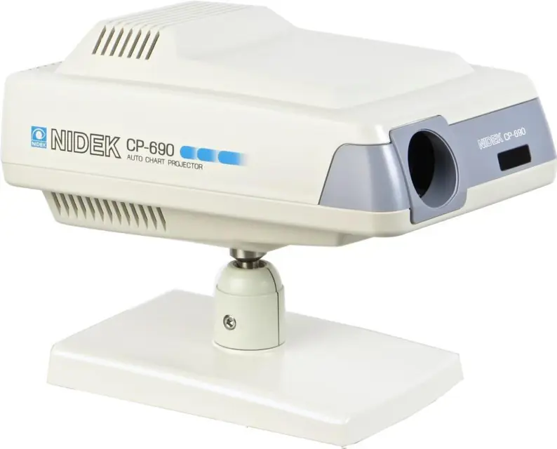
The Nidec Automatic Chart Projector CP-690 is a high-performance projection device designed for precision imaging in various industrial applications. Known for its reliability and advanced optical technology, this model ensures clear and accurate presentations, making it an essential tool for professionals in the field.
Turn manuals into instant answers
with your AI-powered assistantTurn manuals into instant answers
with your AI-powered assistant
Manual for Nidec Automatic Chart Projector CP-690
Complete asset maintenance, one click away
Get instant access to all the maintenance information you need. Empower technicians to perform preventive maintenance with asset packages, ready to use right out of the box.

Documents & Manuals
Find all the essential guides in one place.
 Tensioning Guide
- Belt-diagram
- C-120 pulleys
+ 13 more

Work Order Templates
Pre-built workflows to keep your asset running smoothly.
- Daily Electrical System Inspection
- Replace Roller and Pulley
- Install Engine B-120
+ 29 more

Procedures
Integrate maintenance plans directly into your work orders.
- Motion Industries
- Applied Industrial Technologies
- Electrical Brothers
+ 5 more

Parts
Access the parts list for your equipment in MaintainX.
- Drive Motor
- B2 Rollers
- Tensioning System
+ 40 more
Nidec Automatic Chart Projector CP-690
Create an account to install this asset package.
Maintenance Plans for Nidec Automatic Chart Projector Model CP-690
Integrate maintenance plans directly into your work orders in MaintainX.
Adjustment of Intitialized Position
Warning: This procedure requires technical knowledge and should be performed by trained personnel only.
Top cover ASSY removed
No. 8 of the DIP switch on the BA01 board turned to the ON position
Ensure the main body is installed on a stable and level surface.
Chart projected on the screen and focus roughly adjusted
Operate the remote control as follows so that the first projected chart and open mask become horizontal.
VA UP button pressed to move the chart up
VA DOWN button pressed to move the chart down
START button pressed to move the mask up

Adjustment of the Chart and Mask Positions
Remove the top and bottom cover ASSYs and disk cover (M030)
Turn the power switch ON, project the chart onto the screen and adjust the focus
Loosen SB4 × 10 (n=4) , SW4 (n=4) and PW4 (n=4) fixing the mask motor
Make fine adjustments of the mask motor position to satisfy the conditions
If the adjustment can not be completed by moving the mask motor, move the chart position by making fine adjustments of the chart sensor position
When the chart sensor is moved, perform Adjustment of the fixed mask position
Single letter mask position: When applying the single letter mask to the charts, the alphabetical letter shall be in about the center of the mask
R/G filter position: The boundary between the red and green filters shall be in the middle of the chart horizontally
Blocking of the astigmatism clock dial chart: The projected astigmatism clock dial chart shall be not blocked
Adjustment of the Fixed Mask Position
NOTE! The parts around the lamp become hot. Do not touch the parts directly by hand.
Turn the power switch ON, project the chart on the screen and adjust the focus.
Turn the power switch OFF, remove the top cover ASSY and disk cover (M030).
Disconnect the connectors from J3 and J5 on the BA01 board.
Unscrew BS3 × 6ZnC to remove the VA mask (M029).
Turn the power switch ON again, rotate the chart and mask disks by hand to check the position (tilt) of the fixed mask.
Loosen HH3 × 4 (n=2) to rotate the fixed mask by hand. Adjust it to satisfy the following conditions.
Tighten the loosened screws while pushing the fixed mask into the lamp side.
Assemble the removed parts in reverse order.
Adjustment of the Lamp (LED) Position
NOTE! For variable power lens barrel, set the lens position as below before adjustment.
Remove the top and bottom cover ASSYs and turn the power switch ON.
Place a piece of white paper at a position of 0 to 10 mm from the lower side of the front cover.
The LED image appear on the paper as follows.
Loosen TH screw (n=3) fixing LED ASSY. Adjust the focus of the LED image by pushing and pulling the LED ASSY. Fix TH screw where the reflection image is focused.
Loosen PC screw (n=4) fixing LED ASSY. Move the LED ASSY in order that LED image becomes center of circle. Fix the screw where the reflection image of LED becomes center.
Project the chart onto the screen to check that the chart brightness is even.
Remount the top and bottom cover ASSYs.
Sign off on the lamp adjustment
Adjustment of the Sensor Voltage
Top cover ASSY removed
No. 8 of the DIP switch on the BA01 board turned to the ON position
Warning: When turning the DIP switch to the ON or OFF position, slide the switch without loading the circuit board. If not, a failure may occur.
Voltage between TP1 and TP3 on the BA01 board for chart sensor
Voltage between TP1 and TP3 within the applicable range (4.5 V to 5.0 V)
VA DOWN button on the remote control pressed twice and the VA UP button once
Voltage between TP1 and TP3 on the BA01 board for chart sensor after pressing buttons
Voltage between TP1 and TP3 within the applicable range (0.5 V or less)
VA UP button on the remote control pressed once
Parts for Nidec Automatic Chart Projector CP-690
Access the parts list for your equipment in MaintainX.
1 Chip CPU
33159-E100
1 Chip CPU
33158-E100
1 Chip CPU
33160-E100
1 Chip CPU
33156-E200
1 Chip CPU
33161-E100
1 Chip CPU
33159-E100
1 Chip CPU
33158-E100
1 Chip CPU
33160-E100
1 Chip CPU
33156-E200
1 Chip CPU
33161-E100
1 Chip CPU
33159-E100
1 Chip CPU
33158-E100
1 Chip CPU
33160-E100
1 Chip CPU
33156-E200
1 Chip CPU
33161-E100
Unlock
efficiency with MaintainX Assist
MaintainX Assist is your expert colleague, on call 24/7, helping your team find the answers they need to keep equipment running.
'/%3e%3cpath%20d='M32.0001%2048.6663C22.7953%2048.6663%2015.3335%2041.2043%2015.3335%2031.9997C15.3335%2022.7949%2022.7954%2015.333%2032.0001%2015.333C39.463%2015.333%2045.7096%2020.2378%2047.8335%2026.9997H43.6668'%20stroke='white'%20stroke-width='2.85714'%20stroke-linecap='round'%20stroke-linejoin='round'/%3e%3cpath%20d='M32%2025.333V31.9997L35.3333%2035.333'%20stroke='white'%20stroke-width='2.85714'%20stroke-linecap='round'%20stroke-linejoin='round'/%3e%3cpath%20d='M48.5918%2033.6667C48.6413%2033.1182%2048.6667%2032.5622%2048.6667%2032M37%2048.6667C37.5693%2048.4793%2038.1255%2048.2607%2038.6667%2048.013M46.651%2040.3333C46.9725%2039.714%2047.2592%2039.0722%2047.5083%2038.4103M42.3208%2045.7153C42.8948%2045.2402%2043.4385%2044.7263%2043.948%2044.1775'%20stroke='white'%20stroke-width='2.85714'%20stroke-linecap='round'%20stroke-linejoin='round'/%3e%3cdefs%3e%3clinearGradient%20id='paint0_linear_9036_2820'%20x1='17.4188'%20y1='24.2718'%20x2='46.9529'%20y2='57.2957'%20gradientUnits='userSpaceOnUse'%3e%3cstop%20stop-color='%23246CFF'/%3e%3cstop%20offset='1'%20stop-color='%2321C779'/%3e%3c/linearGradient%3e%3c/defs%3e%3c/svg%3e)
Reduce Unplanned Downtime
Ensure your team follows consistent procedures to minimize equipment failures and costly delays.
'/%3e%3cpath%20d='M15.7599%2038.0533C15.8165%2037.5147%2016.2068%2037.0805%2016.9875%2036.2123L18.706%2034.2912C19.126%2033.7593%2019.4241%2032.833%2019.4241%2031.9993C19.4241%2031.1663%2019.1259%2030.2397%2018.7059%2029.708L16.9875%2027.7869C16.2068%2026.9186%2015.8164%2026.4845%2015.7599%2025.9458C15.7033%2025.4071%2015.9949%2024.9011%2016.578%2023.889L17.4007%2022.4613C18.0228%2021.3816%2018.3339%2020.8417%2018.8632%2020.6265C19.3925%2020.4112%2019.9911%2020.5811%2021.1883%2020.9208L23.2221%2021.4936C23.9864%2021.6699%2024.7883%2021.5699%2025.4862%2021.2113L26.0477%2020.8874C26.6462%2020.504%2027.1065%2019.9389%2027.3613%2019.2746L27.9179%2017.6122C28.2839%2016.5122%2028.4668%2015.9622%2028.9024%2015.6476C29.3381%2015.333%2029.9167%2015.333%2031.0739%2015.333H32.9319C34.0892%2015.333%2034.6679%2015.333%2035.1034%2015.6476C35.5391%2015.9622%2035.7221%2016.5122%2036.0881%2017.6122L36.6446%2019.2746C36.8994%2019.9389%2037.3597%2020.504%2037.9582%2020.8874L38.5197%2021.2113C39.2176%2021.5699%2040.0196%2021.6699%2040.7839%2021.4936L42.8176%2020.9208C44.0147%2020.5811%2044.6134%2020.4112%2045.1427%2020.6265C45.6721%2020.8417%2045.9831%2021.3816%2046.6052%2022.4613L47.4279%2023.889C48.0111%2024.9011%2048.3026%2025.4071%2048.2461%2025.9458C48.1894%2026.4845%2047.7991%2026.9186%2047.0184%2027.7869L45.2999%2029.708C44.8801%2030.2397%2044.5817%2031.1663%2044.5817%2031.9993C44.5817%2032.833%2044.8799%2033.7593%2045.2999%2034.2912L47.0184%2036.2123C47.7991%2037.0805%2048.1894%2037.5147%2048.2461%2038.0533C48.3026%2038.5922%2048.0111%2039.0982%2047.4279%2040.1102L46.6052%2041.5378C45.9831%2042.6175%2045.6721%2043.1575%2045.1427%2043.3727C44.6134%2043.588%2044.0147%2043.4182%2042.8176%2043.0783L40.7839%2042.5055C40.0194%2042.3292%2039.2174%2042.4293%2038.5194%2042.788L37.9581%2043.112C37.3596%2043.4953%2036.8994%2044.0603%2036.6447%2044.7247L36.0881%2046.3872C35.7221%2047.4872%2035.5391%2048.0372%2035.1034%2048.3517C34.6679%2048.6663%2034.0892%2048.6663%2032.9319%2048.6663H31.0739C29.9167%2048.6663%2029.3381%2048.6663%2028.9024%2048.3517C28.4668%2048.0372%2028.2839%2047.4872%2027.9179%2046.3872'%20stroke='white'%20stroke-width='2.85714'%20stroke-linecap='round'/%3e%3cpath%20d='M16.5614%2043.2993C18.3614%2041.4993%2024.4814%2035.4393%2025.0814%2034.7393C25.7157%2033.9993%2025.2014%2032.9993%2025.5074%2029.8993C25.6555%2028.3993%2025.9781%2027.2756%2026.9014%2026.4393C28.0014%2025.3993%2028.9015%2025.3993%2032.0015%2025.3294C34.7015%2025.3993%2035.0215%2025.0993%2035.3015%2025.7994C35.5015%2026.2994%2034.9015%2026.5993%2034.1815%2027.3994C32.5815%2028.9993%2031.6415%2029.7993%2031.5515%2030.2993C30.9015%2032.4993%2033.4615%2033.7993%2034.8615%2032.3993C35.3908%2031.8698%2037.8415%2029.3993%2038.0815%2029.1993C38.2615%2029.0393%2038.6923%2029.047%2038.9015%2029.2993C39.0815%2029.4762%2039.1015%2029.4993%2039.0815%2030.2993C39.063%2031.0398%2039.0712%2032.103%2039.0735%2033.1993C39.0763%2034.6198%2039.0015%2036.1993%2038.4015%2036.9993C37.2015%2038.7993%2035.2015%2038.8993%2033.4015%2038.9793C31.7015%2039.0793%2030.3015%2038.8993%2029.8615%2039.2193C29.5015%2039.3993%2027.6014%2041.3993%2025.3014%2043.6993L21.2014%2047.7993C17.8014%2050.4993%2014.0614%2046.2993%2016.5614%2043.2993Z'%20stroke='white'%20stroke-width='2.85714'%20stroke-linecap='round'/%3e%3cdefs%3e%3clinearGradient%20id='paint0_linear_9036_2840'%20x1='17.4188'%20y1='24.2718'%20x2='46.9529'%20y2='57.2957'%20gradientUnits='userSpaceOnUse'%3e%3cstop%20stop-color='%23246CFF'/%3e%3cstop%20offset='1'%20stop-color='%2321C779'/%3e%3c/linearGradient%3e%3c/defs%3e%3c/svg%3e)
Maximize Asset Availability
Keep your assets running longer and more reliably, with standardized maintenance workflows from OEM manuals.
'/%3e%3cpath%20d='M35.3333%2041.9997C42.6972%2041.9997%2048.6667%2036.0302%2048.6667%2028.6663C48.6667%2021.3025%2042.6972%2015.333%2035.3333%2015.333C27.9695%2015.333%2022%2021.3025%2022%2028.6663C22%2036.0302%2027.9695%2041.9997%2035.3333%2041.9997Z'%20stroke='white'%20stroke-width='2.85714'%20stroke-linecap='round'/%3e%3cpath%20d='M17.2611%2030.333C16.0422%2032.1957%2015.3335%2034.4222%2015.3335%2036.8143C15.3335%2043.36%2020.6398%2048.6663%2027.1854%2048.6663C29.5777%2048.6663%2031.8042%2047.9577%2033.6668%2046.7387'%20stroke='white'%20stroke-width='2.85714'%20stroke-linecap='round'/%3e%3cpath%20d='M38.2854%2025.6752C37.9251%2024.155%2036.0911%2022.7832%2033.8896%2023.8095C31.6881%2024.8357%2031.3384%2028.1376%2034.6684%2028.4884C36.1736%2028.647%2037.1548%2028.3044%2038.0533%2029.2733C38.9516%2030.2422%2039.1186%2032.9365%2036.8219%2033.6627C34.5253%2034.3888%2032.2511%2033.2542%2032.0034%2031.6432M35.3104%2022.0068V23.4552M35.3104%2033.8862V35.3402'%20stroke='white'%20stroke-width='2.85714'%20stroke-linecap='round'%20stroke-linejoin='round'/%3e%3cdefs%3e%3clinearGradient%20id='paint0_linear_9036_2830'%20x1='17.4188'%20y1='24.2718'%20x2='46.9529'%20y2='57.2957'%20gradientUnits='userSpaceOnUse'%3e%3cstop%20stop-color='%23246CFF'/%3e%3cstop%20offset='1'%20stop-color='%2321C779'/%3e%3c/linearGradient%3e%3c/defs%3e%3c/svg%3e)
Lower Maintenance Costs
Turn any technician into an expert to streamline operations, maintain more assets, and reduce overall costs.
Thousands of companies manage their assets with MaintainX

'%3e%3cpath%20fill='url(%23b)'%20d='M66.008%2080.068c-5.084-.786-9.763-3.834-12.442-8.68a16.942%2016.942%200%200%201-1.87-5.18c1.096.19%202.203.476%203.298.87%206.525%202.333%2010.836%207.68%2011.014%2012.99ZM51.47%2061.576c.488-5.524%203.62-10.716%208.847-13.597a17.132%2017.132%200%200%201%2011.335-1.882c-.798%208.145-7.43%2014.848-16.038%2015.599-1.417.119-2.799.07-4.144-.12Zm28.564-11.478a17.513%2017.513%200%200%201%203.727%204.62c4.608%208.335%201.584%2018.813-6.75%2023.409a16.988%2016.988%200%200%201-4.359%201.679%2019.624%2019.624%200%200%201-3.977-12.776c.346-7.561%204.942-13.931%2011.36-16.932Z'/%3e%3cpath%20fill='%23110F0D'%20fill-rule='evenodd'%20d='M142.831%2048.324h4.977V77.03h-4.977V48.324Zm27.278%2013.002c.322%201.048.453%202.263.453%203.62v12.073h-4.787V66.208c0-.75-.047-1.572-.154-2.143-.453-2.382-1.822-3.572-4.215-3.572-2.31%200-3.882%201.274-4.43%203.476-.143.596-.226%201.405-.226%202.25v10.8h-4.787V56.623h4.477v2.989c1.536-2.5%203.906-3.43%206.371-3.43%203.488%200%206.263%201.68%207.298%205.144Zm24.636%207.323c0%203.882-2.358%206.525-5.763%207.727-1.298.453-2.632.643-4.62.643h-10.169V48.324h9.085c1.691%200%203.156.143%204.049.38%203.465.93%205.727%203.68%205.727%207.335%200%202.441-.81%204.156-2.762%205.644%202.905%201.417%204.453%203.727%204.453%206.966Zm-15.634-8.656h4.584c1.024%200%201.917-.143%202.536-.417%201.215-.548%201.905-1.608%201.905-3.167%200-1.548-.643-2.572-1.845-3.132-.691-.31-1.762-.452-2.763-.452h-4.417v7.168Zm10.716%208.465c0-1.536-.893-3.37-3.227-3.893-.428-.095-1.036-.143-1.571-.143h-5.918v8.085h5.501c.56%200%201.429-.048%201.953-.167%201.94-.453%203.262-1.846%203.262-3.882Zm47.747-11.847-8.097%2020.408h-4.429l-8.109-20.408h5.191l5.192%2014.574%205.108-14.574h5.144Zm-20.218%2010.002c0%20.69-.036%201.262-.155%201.94h-15.943c.631%202.87%202.714%204.728%205.882%204.728%202.131%200%203.607-.882%204.703-2.525h4.87c-1.762%204.144-5.204%206.692-9.657%206.692-6.084%200-10.537-4.858-10.537-10.49%200-6.108%204.524-10.776%2010.335-10.776%206.239%200%2010.442%204.954%2010.502%2010.43Zm-4.763-1.405c-.333-2.846-2.643-4.858-5.691-4.858-2.894%200-5.287%201.929-5.621%204.858h11.312Zm-72.667%203.44c0%204.787-3.287%208.371-9.419%208.371H119.363V64.66c-1.917.274-3.87.69-5.811%201.238l4.537%2011.121h-5.418l-3.596-9.585c-5.144%202.084-10.085%205.216-14.217%209.585h-4.786L101.8%2048.312h4.56l5.68%2013.883a44.112%2044.112%200%200%201%207.323-1.774V48.312h9.084c1.703%200%203.156.143%204.061.393%203.453.929%205.727%203.667%205.727%207.323%200%201.917-.738%204.179-2.81%205.691%203.06%201.56%204.501%204.025%204.501%206.93Zm-15.634-8.667a62.664%2062.664%200%200%201%202.06-.036c1.703.012%203.239.131%204.608.37%201.441-.549%202.357-1.727%202.357-3.537%200-1.941-.881-3.144-2.488-3.667-.548-.18-1.358-.286-2.322-.286h-4.215v7.156Zm-16.55%203.905-3.715-9.894-6.394%2016.502c2.833-2.595%206.263-4.858%2010.109-6.608Zm27.254%204.74c0-2.775-3.131-4.347-8.513-4.418-.715%200-1.441.011-2.191.047v8.252h5.918c2.548%200%204.786-1.37%204.786-3.882Z'%20clip-rule='evenodd'/%3e%3c/g%3e%3cdefs%3e%3clinearGradient%20id='b'%20x1='51.47'%20x2='85.916'%20y1='62.946'%20y2='62.946'%20gradientUnits='userSpaceOnUse'%3e%3cstop%20stop-color='%23CD9F28'/%3e%3cstop%20offset='1'%20stop-color='%23ECD80B'/%3e%3c/linearGradient%3e%3cclipPath%20id='a'%3e%3cpath%20fill='%23fff'%20d='M51.47%2045.728h186.104V80.14H51.47z'/%3e%3c/clipPath%3e%3c/defs%3e%3c/svg%3e)











More from Nidec

Explore Other Assets





© 2026 MaintainX. All rights reserved.