


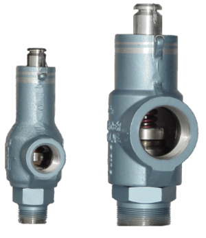
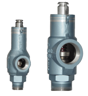
Mercer Valve Pressure Relief Valve 81-12151V18G11
Need answers fast?
Explore the manual using AI.

Turn manuals into instant answers
with your AI-powered assistantTurn manuals into instant answers
with your AI-powered assistant
Manual for Mercer Valve Pressure Relief Valve 81-12151V18G11
Complete asset maintenance, one click away
Get instant access to all the maintenance information you need. Empower technicians to perform preventive maintenance with asset packages, ready to use right out of the box.

Documents & Manuals
Find all the essential guides in one place.
 Tensioning Guide
- Belt-diagram
- C-120 pulleys
+ 13 more

Work Order Templates
Pre-built workflows to keep your asset running smoothly.
- Daily Electrical System Inspection
- Replace Roller and Pulley
- Install Engine B-120
+ 29 more

Procedures
Integrate maintenance plans directly into your work orders.
- Motion Industries
- Applied Industrial Technologies
- Electrical Brothers
+ 5 more

Parts
Access the parts list for your equipment in MaintainX.
- Drive Motor
- B2 Rollers
- Tensioning System
+ 40 more
Mercer Valve Pressure Relief Valve 81-12151V18G11
Create an account to install this asset package.
Maintenance Plans for Mercer Valve Pressure Relief Valve Model 81-12151V18G11
Integrate maintenance plans directly into your work orders in MaintainX.
1 Yearly Pressure Relief Valve Visual Inspection
Warning: Ensure the valve is not pressurized before starting the inspection
Cap and Seal Wire in good condition
Security seal on the seal wire intact
Flanges Connections in good condition
Threaded Connection in good condition
Outlet free from corrosion or debris accumulation
External Surface free from damage
Valve Tag information corresponds to the service conditions
Set pressure, CDTP, and capacity in appropriate unit of measure for the service fluid verified

1 Yearly Pressure Relief Valve Set Pressure Inspection
During the set pressure inspection, the set pressure is verified in accordance with the ASME BPVC.
For all valves set 70psi (500kPa) and above, the set pressure has a tolerance of $3% of the set pressure.
For all set pressure below 70psi (500kPa) the tolerance is (±2psi ((±15kPa).
If the valve has a CDTP associated with it due to temperature and/or backpressure, the test pressure is checked to the CDTP.; Even with a CDTP the set pressure tolerance is calculated based on the actual nameplate set pressure.; The set pressure test should be performed before and after any repairs.
The set pressure is inspected to the definition listed in NB-18, a publication by the National Board of Pressure Vessel Inspectors, which is found at http://www.nationalboard.org/.
This publication lists all ASME BPVC certified pressure relief valves.
It indicates the correct set pressure definition and other characteristics of a valve.; The set pressure has been defined to achieve a particular operational characteristics.; If the wrong set pressure definition is used in the inspection test, the valve's set pressure will not be accurate and it may not operate appropriately.
The correct fluid for testing has to be used to achieve accurate results.; For gas/vapor service, nitrogen or compressed air is used as the test fluid, while for liquid service, water is used.; If the incorrect fluid is used during the testing, the test's results will be inaccurate.; Depending on the size of the valve and its set pressure, the set pressure discrepancy can vary outside of ASME tolerances.
Setting procedures should be in accordance with ASME PTC 25.; The rate of the system pressure increase should be slow when the pressure is within 15% of the set pressure. Within this range, the rate should never be more than 2psi/sec (15kPa/sec).; Ideally each pressure increment on the pressure gauge should be clearly read as the pressure is increased. Slow pressure increase helps to accurately read the pressure gauge.
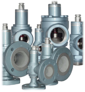
Pressure Relief Valve Maintenance
The following general procedure is recommended for the disassembling of a Mercer 8100 Series PRV.; Non-standard, “special”, configurations are possible and these instructions may not be reflective of them; a special configuration is indicated by a special code at the end of the PRV’s part number.; Always make sure there is no pressure in the system prior to removing a PRV.
These instructions are divided into two sections: 1” Body and 2” Body.
a) 1” Body
1. Cut and remove the seal wire and unscrew the cap to expose the adjustment screw.
i) Go to "c" if the valve is a lift lever configuration.
2. Loosen the lock nut from the adjustment screw.
3. Relieve the compression on the spring by turning the adjustment screw counter clockwise.; This is important so that components will not spring out and pose a hazard.; If the adjustment screw begins to appear as residing back into the bonnet during the relieving of the preload, then the spring compression has been completely removed and the adjustment bushing is beginning to re-compress the spring.
4. Rigidly support the body to prevent movement during disassembly.
5. Unscrew the inlet base using the appropriate wrenching flats.; 6. Remove the set spring and discard the disk subassembly.
1 Yearly Pressure Relief Valve Leak Inspection
After the set pressure is verified, the valve undergoes a leak inspection.
This is performed to verify the disk and seat are sealed to a degree appropriate for the type of pressure relief valve being tested.
Leak tests are always performed below the set pressure of the valve, usually at a certain percentage of the set pressure.
The leak check is usually performed at 90% of the set pressure or 5psi (34.5kPa) below the set pressure, whichever is greater.
If the valve has a CDTP, the leak test pressure will be below the CDTP in lieu of the set pressure.
Mercer Valve Co. Inc. should be contacted for proper leak pressure and specification for the valve.
In the tests, the pressure is held steady for a length of time and any leakage is observed.
Before this test is performed, the valve must have had its set pressure examined.
There are several methods used in testing for leakage.
Pressure Relief Valve Component Inspection
The following general procedure is recommended for the inspection of an 8100 Series PRV.
New parts should be inspected.
1. Inspect the seat for cuts and abrasions. The seat is the non-metallic element in the nozzle subassembly.
a) If there are only minor scratches or abrasions, the seat may be polished and restored.
b) Polish the seat area lightly with a fine grade abrasive pad. Be careful not to damage the soft seat.
c) If the seat is damaged with deep abrasions and cuts, it should be replaced.
2. Referring to Figure 29, measure the diameter Ds of the nozzle. This diameter must be in the range of values listed in Table
ORIFICE SIZE - ½", NOZZLE DIAMETER Ds, in (mm), 0.620 (15.75) - MINIMUM, 0.622 (15.80) - MAXIMUM
ORIFICE SIZE -¾", NOZZLE DIAMETER Ds, in (mm) 0.914 (23.22) - MINIMUM, 0.916 (23.27) - MAXIMUM
Unlock efficiency
with MaintainX CoPilot
MaintainX CoPilot is your expert colleague, on call 24/7, helping your team find the answers they need to keep equipment running.
Reduce Unplanned Downtime
Ensure your team follows consistent procedures to minimize equipment failures and costly delays.
Maximize Asset Availability
Keep your assets running longer and more reliably, with standardized maintenance workflows from OEM manuals.
Lower Maintenance Costs
Turn any technician into an expert to streamline operations, maintain more assets, and reduce overall costs.
Thousands of companies manage their assets with MaintainX

'%3e%3cpath%20fill='url(%23b)'%20d='M66.008%2080.068c-5.084-.786-9.763-3.834-12.442-8.68a16.942%2016.942%200%200%201-1.87-5.18c1.096.19%202.203.476%203.298.87%206.525%202.333%2010.836%207.68%2011.014%2012.99ZM51.47%2061.576c.488-5.524%203.62-10.716%208.847-13.597a17.132%2017.132%200%200%201%2011.335-1.882c-.798%208.145-7.43%2014.848-16.038%2015.599-1.417.119-2.799.07-4.144-.12Zm28.564-11.478a17.513%2017.513%200%200%201%203.727%204.62c4.608%208.335%201.584%2018.813-6.75%2023.409a16.988%2016.988%200%200%201-4.359%201.679%2019.624%2019.624%200%200%201-3.977-12.776c.346-7.561%204.942-13.931%2011.36-16.932Z'/%3e%3cpath%20fill='%23110F0D'%20fill-rule='evenodd'%20d='M142.831%2048.324h4.977V77.03h-4.977V48.324Zm27.278%2013.002c.322%201.048.453%202.263.453%203.62v12.073h-4.787V66.208c0-.75-.047-1.572-.154-2.143-.453-2.382-1.822-3.572-4.215-3.572-2.31%200-3.882%201.274-4.43%203.476-.143.596-.226%201.405-.226%202.25v10.8h-4.787V56.623h4.477v2.989c1.536-2.5%203.906-3.43%206.371-3.43%203.488%200%206.263%201.68%207.298%205.144Zm24.636%207.323c0%203.882-2.358%206.525-5.763%207.727-1.298.453-2.632.643-4.62.643h-10.169V48.324h9.085c1.691%200%203.156.143%204.049.38%203.465.93%205.727%203.68%205.727%207.335%200%202.441-.81%204.156-2.762%205.644%202.905%201.417%204.453%203.727%204.453%206.966Zm-15.634-8.656h4.584c1.024%200%201.917-.143%202.536-.417%201.215-.548%201.905-1.608%201.905-3.167%200-1.548-.643-2.572-1.845-3.132-.691-.31-1.762-.452-2.763-.452h-4.417v7.168Zm10.716%208.465c0-1.536-.893-3.37-3.227-3.893-.428-.095-1.036-.143-1.571-.143h-5.918v8.085h5.501c.56%200%201.429-.048%201.953-.167%201.94-.453%203.262-1.846%203.262-3.882Zm47.747-11.847-8.097%2020.408h-4.429l-8.109-20.408h5.191l5.192%2014.574%205.108-14.574h5.144Zm-20.218%2010.002c0%20.69-.036%201.262-.155%201.94h-15.943c.631%202.87%202.714%204.728%205.882%204.728%202.131%200%203.607-.882%204.703-2.525h4.87c-1.762%204.144-5.204%206.692-9.657%206.692-6.084%200-10.537-4.858-10.537-10.49%200-6.108%204.524-10.776%2010.335-10.776%206.239%200%2010.442%204.954%2010.502%2010.43Zm-4.763-1.405c-.333-2.846-2.643-4.858-5.691-4.858-2.894%200-5.287%201.929-5.621%204.858h11.312Zm-72.667%203.44c0%204.787-3.287%208.371-9.419%208.371H119.363V64.66c-1.917.274-3.87.69-5.811%201.238l4.537%2011.121h-5.418l-3.596-9.585c-5.144%202.084-10.085%205.216-14.217%209.585h-4.786L101.8%2048.312h4.56l5.68%2013.883a44.112%2044.112%200%200%201%207.323-1.774V48.312h9.084c1.703%200%203.156.143%204.061.393%203.453.929%205.727%203.667%205.727%207.323%200%201.917-.738%204.179-2.81%205.691%203.06%201.56%204.501%204.025%204.501%206.93Zm-15.634-8.667a62.664%2062.664%200%200%201%202.06-.036c1.703.012%203.239.131%204.608.37%201.441-.549%202.357-1.727%202.357-3.537%200-1.941-.881-3.144-2.488-3.667-.548-.18-1.358-.286-2.322-.286h-4.215v7.156Zm-16.55%203.905-3.715-9.894-6.394%2016.502c2.833-2.595%206.263-4.858%2010.109-6.608Zm27.254%204.74c0-2.775-3.131-4.347-8.513-4.418-.715%200-1.441.011-2.191.047v8.252h5.918c2.548%200%204.786-1.37%204.786-3.882Z'%20clip-rule='evenodd'/%3e%3c/g%3e%3cdefs%3e%3clinearGradient%20id='b'%20x1='51.47'%20x2='85.916'%20y1='62.946'%20y2='62.946'%20gradientUnits='userSpaceOnUse'%3e%3cstop%20stop-color='%23CD9F28'/%3e%3cstop%20offset='1'%20stop-color='%23ECD80B'/%3e%3c/linearGradient%3e%3cclipPath%20id='a'%3e%3cpath%20fill='%23fff'%20d='M51.47%2045.728h186.104V80.14H51.47z'/%3e%3c/clipPath%3e%3c/defs%3e%3c/svg%3e)


More from Mercer Valve


Explore Other Assets


© 2026 MaintainX. All rights reserved.