


'%3e%3cpath%20d='M10%2010.5V17h12.5v5.5l-21%20.038V15l8.5-4.5ZM1%206h11M6.5%202H12M5.5%2022.5V19'/%3e%3cpath%20d='M21.21%2017.012%2020.14%201.5h-4.28l-1.07%2015.512M15.516%206.49h4.967'/%3e%3c/g%3e%3cdefs%3e%3cclipPath%20id='a'%3e%3cpath%20fill='%23fff'%20d='M0%200h24v24H0z'/%3e%3c/clipPath%3e%3c/defs%3e%3c/svg%3e)











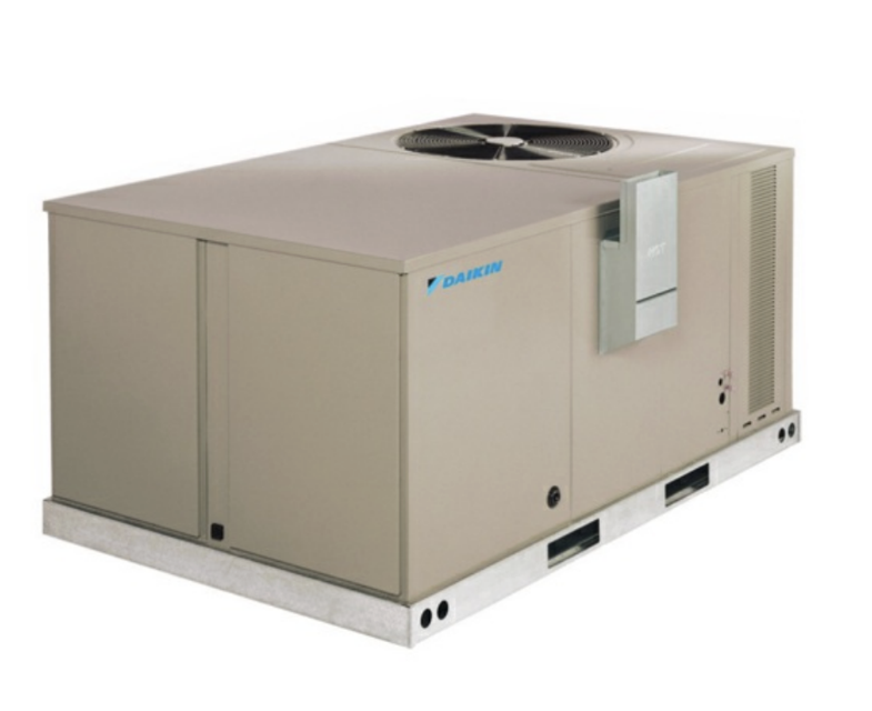
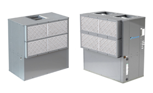
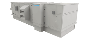
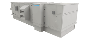
Daikin Rooftop Unit MPSH05
Need answers fast?
Explore the manual using AI.
Turn manuals into instant answers
with your AI-powered assistantTurn manuals into instant answers
with your AI-powered assistant
Manual for Daikin Rooftop Unit MPSH05
Complete asset maintenance, one click away
Get instant access to all the maintenance information you need. Empower technicians to perform preventive maintenance with asset packages, ready to use right out of the box.

Documents & Manuals
Find all the essential guides in one place.
 Tensioning Guide
- Belt-diagram
- C-120 pulleys
+ 13 more

Work Order Templates
Pre-built workflows to keep your asset running smoothly.
- Daily Electrical System Inspection
- Replace Roller and Pulley
- Install Engine B-120
+ 29 more

Procedures
Integrate maintenance plans directly into your work orders.
- Motion Industries
- Applied Industrial Technologies
- Electrical Brothers
+ 5 more

Parts
Access the parts list for your equipment in MaintainX.
- Drive Motor
- B2 Rollers
- Tensioning System
+ 40 more
Daikin Rooftop Unit MPSH05
Create an account to install this asset package.
Maintenance Plans for Daikin Rooftop Unit Model MPSH05
Integrate maintenance plans directly into your work orders in MaintainX.
Blower Motor Speed Change
Warning: Only trained personnel should perform this procedure.
Blower access panel removed
Reference Figure 44 for location of the speed tap block on the blower
Furnace control access panel removed
Control box cover removed
See Figure 45 for location of the integrated furnace control board
Reference Figure 44 and Figure 46 for the proper location of the red and black wires on the speed tap block and on the furnace integrated control board to obtain the speed tap you have chosen
Wires adjusted accordingly
Control box cover attached

Cooling Section Maintenance
DANGER
Power supply to unit must be disconnected before making field connections
To avoid electrical shock, personal injury or death, be sure to rigorously adhere to field wiring procedures regarding proper lockout and tagout of components
It is recommended that at the beginning of each cooling season a qualified installer or service agency inspect and clean the cooling section of this unit
The following areas should be addressed:
Evaporator coil
Condenser coil
Condenser fan motor
Venturi area
Furnace Cleaning
Furnace Section
DANGER: Power supply to unit must be disconnected before making field connections. To avoid electrical shock, personal injury or death, be sure to rigorously adhere to field wiring procedures regarding proper lockout and tagout of components.
DANGER: Holes in the exhaust transition or heat exchanger can cause toxic fumes to enter the building. The exhaust transition or heat exchanger must be replaced if they have holes or cracks in them. Failure to do so can cause carbon monoxide poisoning resulting in personal injury or death.
The unit’s furnace should operate for many years without excessive scale build-up in flue passageways. However, it is recommended that a qualified installer, service agency, or the gas supplier annually inspect the flue passageways, the exhaust system and the burners for continued safe operation, paying particular attention to deterioration from corrosion or other sources.
Turn OFF the electrical power to the unit and set the thermostat to the lowest temperature
Shut OFF the gas supply to the unit either at the meter or at manual valve in the supply piping
Remove the furnace controls access panel and the control box cover. Disconnect the gas supply piping from the gas valve
Disconnect the wiring to the induced draft blower motor, gas valve, flame sensor, and flame roll-out control, and ignitor cable. Mark all wires disconnected for proper reconnection
Remove the screws (4) connecting the burner tray to the heat exchanger mounting panel. Remove the burner tray and the manifold assembly from the unit
Furnace Input Adjustment
Warning: This procedure requires trained personnel with PPE!
Natural Gas Line Pressure
LP Gas Line Pressure
Natural Gas Manifold Pressure
LP Gas Manifold Pressure
Supply and manifold pressure taps are located on the gas valve body 1/8\ N.P.T. and on the manifold"
Use a properly calibrated manometer gauge for accurate gas pressure readings
Only small variations in the gas flow should be made by means of the pressure regulator adjustment
Furnaces functioning on LP gas must be set by means of the tank or branch supply regulators
Motors Maintenance
Note: The blower motor and induced draft blower motor are prelubricated by the manufacturer and do not require further attention.
A qualified installer, service agency or the gas supplier must periodically clean the motors to prevent the possibility of overheating due to an accumulation of dust and dirt on the windings or on the motor exterior.
Are the air filters clean?
The motor depends upon sufficient air flowing across and through it to prevent overheating.
Is there sufficient air flow across and through the motor?
Sign off on the motor maintenance
Parts for Daikin Rooftop Unit MPSH05
Access the parts list for your equipment in MaintainX.
14" Roof Curb, 3–5 Ton
RXKG-CBH14
7-Day Programmable Stat
113129901
CO₂ Sensor
RXRX-AR02
Dual Enthalpy Kit
RXRX-AV02
Economizer, Analog Controls, 3–5 Ton, Vert/Horiz
MXRD-01RECAM3
14" Roof Curb, 3–5 Ton
RXKG-CBH14
7-Day Programmable Stat
113129901
CO₂ Sensor
RXRX-AR02
Dual Enthalpy Kit
RXRX-AV02
Economizer, Analog Controls, 3–5 Ton, Vert/Horiz
MXRD-01RECAM3
14" Roof Curb, 3–5 Ton
RXKG-CBH14
7-Day Programmable Stat
113129901
CO₂ Sensor
RXRX-AR02
Dual Enthalpy Kit
RXRX-AV02
Economizer, Analog Controls, 3–5 Ton, Vert/Horiz
MXRD-01RECAM3
Unlock
efficiency with MaintainX Assist
MaintainX Assist is your expert colleague, on call 24/7, helping your team find the answers they need to keep equipment running.
'/%3e%3cpath%20d='M32.0001%2048.6663C22.7953%2048.6663%2015.3335%2041.2043%2015.3335%2031.9997C15.3335%2022.7949%2022.7954%2015.333%2032.0001%2015.333C39.463%2015.333%2045.7096%2020.2378%2047.8335%2026.9997H43.6668'%20stroke='white'%20stroke-width='2.85714'%20stroke-linecap='round'%20stroke-linejoin='round'/%3e%3cpath%20d='M32%2025.333V31.9997L35.3333%2035.333'%20stroke='white'%20stroke-width='2.85714'%20stroke-linecap='round'%20stroke-linejoin='round'/%3e%3cpath%20d='M48.5918%2033.6667C48.6413%2033.1182%2048.6667%2032.5622%2048.6667%2032M37%2048.6667C37.5693%2048.4793%2038.1255%2048.2607%2038.6667%2048.013M46.651%2040.3333C46.9725%2039.714%2047.2592%2039.0722%2047.5083%2038.4103M42.3208%2045.7153C42.8948%2045.2402%2043.4385%2044.7263%2043.948%2044.1775'%20stroke='white'%20stroke-width='2.85714'%20stroke-linecap='round'%20stroke-linejoin='round'/%3e%3cdefs%3e%3clinearGradient%20id='paint0_linear_9036_2820'%20x1='17.4188'%20y1='24.2718'%20x2='46.9529'%20y2='57.2957'%20gradientUnits='userSpaceOnUse'%3e%3cstop%20stop-color='%23246CFF'/%3e%3cstop%20offset='1'%20stop-color='%2321C779'/%3e%3c/linearGradient%3e%3c/defs%3e%3c/svg%3e)
Reduce Unplanned Downtime
Ensure your team follows consistent procedures to minimize equipment failures and costly delays.
'/%3e%3cpath%20d='M15.7599%2038.0533C15.8165%2037.5147%2016.2068%2037.0805%2016.9875%2036.2123L18.706%2034.2912C19.126%2033.7593%2019.4241%2032.833%2019.4241%2031.9993C19.4241%2031.1663%2019.1259%2030.2397%2018.7059%2029.708L16.9875%2027.7869C16.2068%2026.9186%2015.8164%2026.4845%2015.7599%2025.9458C15.7033%2025.4071%2015.9949%2024.9011%2016.578%2023.889L17.4007%2022.4613C18.0228%2021.3816%2018.3339%2020.8417%2018.8632%2020.6265C19.3925%2020.4112%2019.9911%2020.5811%2021.1883%2020.9208L23.2221%2021.4936C23.9864%2021.6699%2024.7883%2021.5699%2025.4862%2021.2113L26.0477%2020.8874C26.6462%2020.504%2027.1065%2019.9389%2027.3613%2019.2746L27.9179%2017.6122C28.2839%2016.5122%2028.4668%2015.9622%2028.9024%2015.6476C29.3381%2015.333%2029.9167%2015.333%2031.0739%2015.333H32.9319C34.0892%2015.333%2034.6679%2015.333%2035.1034%2015.6476C35.5391%2015.9622%2035.7221%2016.5122%2036.0881%2017.6122L36.6446%2019.2746C36.8994%2019.9389%2037.3597%2020.504%2037.9582%2020.8874L38.5197%2021.2113C39.2176%2021.5699%2040.0196%2021.6699%2040.7839%2021.4936L42.8176%2020.9208C44.0147%2020.5811%2044.6134%2020.4112%2045.1427%2020.6265C45.6721%2020.8417%2045.9831%2021.3816%2046.6052%2022.4613L47.4279%2023.889C48.0111%2024.9011%2048.3026%2025.4071%2048.2461%2025.9458C48.1894%2026.4845%2047.7991%2026.9186%2047.0184%2027.7869L45.2999%2029.708C44.8801%2030.2397%2044.5817%2031.1663%2044.5817%2031.9993C44.5817%2032.833%2044.8799%2033.7593%2045.2999%2034.2912L47.0184%2036.2123C47.7991%2037.0805%2048.1894%2037.5147%2048.2461%2038.0533C48.3026%2038.5922%2048.0111%2039.0982%2047.4279%2040.1102L46.6052%2041.5378C45.9831%2042.6175%2045.6721%2043.1575%2045.1427%2043.3727C44.6134%2043.588%2044.0147%2043.4182%2042.8176%2043.0783L40.7839%2042.5055C40.0194%2042.3292%2039.2174%2042.4293%2038.5194%2042.788L37.9581%2043.112C37.3596%2043.4953%2036.8994%2044.0603%2036.6447%2044.7247L36.0881%2046.3872C35.7221%2047.4872%2035.5391%2048.0372%2035.1034%2048.3517C34.6679%2048.6663%2034.0892%2048.6663%2032.9319%2048.6663H31.0739C29.9167%2048.6663%2029.3381%2048.6663%2028.9024%2048.3517C28.4668%2048.0372%2028.2839%2047.4872%2027.9179%2046.3872'%20stroke='white'%20stroke-width='2.85714'%20stroke-linecap='round'/%3e%3cpath%20d='M16.5614%2043.2993C18.3614%2041.4993%2024.4814%2035.4393%2025.0814%2034.7393C25.7157%2033.9993%2025.2014%2032.9993%2025.5074%2029.8993C25.6555%2028.3993%2025.9781%2027.2756%2026.9014%2026.4393C28.0014%2025.3993%2028.9015%2025.3993%2032.0015%2025.3294C34.7015%2025.3993%2035.0215%2025.0993%2035.3015%2025.7994C35.5015%2026.2994%2034.9015%2026.5993%2034.1815%2027.3994C32.5815%2028.9993%2031.6415%2029.7993%2031.5515%2030.2993C30.9015%2032.4993%2033.4615%2033.7993%2034.8615%2032.3993C35.3908%2031.8698%2037.8415%2029.3993%2038.0815%2029.1993C38.2615%2029.0393%2038.6923%2029.047%2038.9015%2029.2993C39.0815%2029.4762%2039.1015%2029.4993%2039.0815%2030.2993C39.063%2031.0398%2039.0712%2032.103%2039.0735%2033.1993C39.0763%2034.6198%2039.0015%2036.1993%2038.4015%2036.9993C37.2015%2038.7993%2035.2015%2038.8993%2033.4015%2038.9793C31.7015%2039.0793%2030.3015%2038.8993%2029.8615%2039.2193C29.5015%2039.3993%2027.6014%2041.3993%2025.3014%2043.6993L21.2014%2047.7993C17.8014%2050.4993%2014.0614%2046.2993%2016.5614%2043.2993Z'%20stroke='white'%20stroke-width='2.85714'%20stroke-linecap='round'/%3e%3cdefs%3e%3clinearGradient%20id='paint0_linear_9036_2840'%20x1='17.4188'%20y1='24.2718'%20x2='46.9529'%20y2='57.2957'%20gradientUnits='userSpaceOnUse'%3e%3cstop%20stop-color='%23246CFF'/%3e%3cstop%20offset='1'%20stop-color='%2321C779'/%3e%3c/linearGradient%3e%3c/defs%3e%3c/svg%3e)
Maximize Asset Availability
Keep your assets running longer and more reliably, with standardized maintenance workflows from OEM manuals.
'/%3e%3cpath%20d='M35.3333%2041.9997C42.6972%2041.9997%2048.6667%2036.0302%2048.6667%2028.6663C48.6667%2021.3025%2042.6972%2015.333%2035.3333%2015.333C27.9695%2015.333%2022%2021.3025%2022%2028.6663C22%2036.0302%2027.9695%2041.9997%2035.3333%2041.9997Z'%20stroke='white'%20stroke-width='2.85714'%20stroke-linecap='round'/%3e%3cpath%20d='M17.2611%2030.333C16.0422%2032.1957%2015.3335%2034.4222%2015.3335%2036.8143C15.3335%2043.36%2020.6398%2048.6663%2027.1854%2048.6663C29.5777%2048.6663%2031.8042%2047.9577%2033.6668%2046.7387'%20stroke='white'%20stroke-width='2.85714'%20stroke-linecap='round'/%3e%3cpath%20d='M38.2854%2025.6752C37.9251%2024.155%2036.0911%2022.7832%2033.8896%2023.8095C31.6881%2024.8357%2031.3384%2028.1376%2034.6684%2028.4884C36.1736%2028.647%2037.1548%2028.3044%2038.0533%2029.2733C38.9516%2030.2422%2039.1186%2032.9365%2036.8219%2033.6627C34.5253%2034.3888%2032.2511%2033.2542%2032.0034%2031.6432M35.3104%2022.0068V23.4552M35.3104%2033.8862V35.3402'%20stroke='white'%20stroke-width='2.85714'%20stroke-linecap='round'%20stroke-linejoin='round'/%3e%3cdefs%3e%3clinearGradient%20id='paint0_linear_9036_2830'%20x1='17.4188'%20y1='24.2718'%20x2='46.9529'%20y2='57.2957'%20gradientUnits='userSpaceOnUse'%3e%3cstop%20stop-color='%23246CFF'/%3e%3cstop%20offset='1'%20stop-color='%2321C779'/%3e%3c/linearGradient%3e%3c/defs%3e%3c/svg%3e)
Lower Maintenance Costs
Turn any technician into an expert to streamline operations, maintain more assets, and reduce overall costs.
Thousands of companies manage their assets with MaintainX

'%3e%3cpath%20fill='url(%23b)'%20d='M66.008%2080.068c-5.084-.786-9.763-3.834-12.442-8.68a16.942%2016.942%200%200%201-1.87-5.18c1.096.19%202.203.476%203.298.87%206.525%202.333%2010.836%207.68%2011.014%2012.99ZM51.47%2061.576c.488-5.524%203.62-10.716%208.847-13.597a17.132%2017.132%200%200%201%2011.335-1.882c-.798%208.145-7.43%2014.848-16.038%2015.599-1.417.119-2.799.07-4.144-.12Zm28.564-11.478a17.513%2017.513%200%200%201%203.727%204.62c4.608%208.335%201.584%2018.813-6.75%2023.409a16.988%2016.988%200%200%201-4.359%201.679%2019.624%2019.624%200%200%201-3.977-12.776c.346-7.561%204.942-13.931%2011.36-16.932Z'/%3e%3cpath%20fill='%23110F0D'%20fill-rule='evenodd'%20d='M142.831%2048.324h4.977V77.03h-4.977V48.324Zm27.278%2013.002c.322%201.048.453%202.263.453%203.62v12.073h-4.787V66.208c0-.75-.047-1.572-.154-2.143-.453-2.382-1.822-3.572-4.215-3.572-2.31%200-3.882%201.274-4.43%203.476-.143.596-.226%201.405-.226%202.25v10.8h-4.787V56.623h4.477v2.989c1.536-2.5%203.906-3.43%206.371-3.43%203.488%200%206.263%201.68%207.298%205.144Zm24.636%207.323c0%203.882-2.358%206.525-5.763%207.727-1.298.453-2.632.643-4.62.643h-10.169V48.324h9.085c1.691%200%203.156.143%204.049.38%203.465.93%205.727%203.68%205.727%207.335%200%202.441-.81%204.156-2.762%205.644%202.905%201.417%204.453%203.727%204.453%206.966Zm-15.634-8.656h4.584c1.024%200%201.917-.143%202.536-.417%201.215-.548%201.905-1.608%201.905-3.167%200-1.548-.643-2.572-1.845-3.132-.691-.31-1.762-.452-2.763-.452h-4.417v7.168Zm10.716%208.465c0-1.536-.893-3.37-3.227-3.893-.428-.095-1.036-.143-1.571-.143h-5.918v8.085h5.501c.56%200%201.429-.048%201.953-.167%201.94-.453%203.262-1.846%203.262-3.882Zm47.747-11.847-8.097%2020.408h-4.429l-8.109-20.408h5.191l5.192%2014.574%205.108-14.574h5.144Zm-20.218%2010.002c0%20.69-.036%201.262-.155%201.94h-15.943c.631%202.87%202.714%204.728%205.882%204.728%202.131%200%203.607-.882%204.703-2.525h4.87c-1.762%204.144-5.204%206.692-9.657%206.692-6.084%200-10.537-4.858-10.537-10.49%200-6.108%204.524-10.776%2010.335-10.776%206.239%200%2010.442%204.954%2010.502%2010.43Zm-4.763-1.405c-.333-2.846-2.643-4.858-5.691-4.858-2.894%200-5.287%201.929-5.621%204.858h11.312Zm-72.667%203.44c0%204.787-3.287%208.371-9.419%208.371H119.363V64.66c-1.917.274-3.87.69-5.811%201.238l4.537%2011.121h-5.418l-3.596-9.585c-5.144%202.084-10.085%205.216-14.217%209.585h-4.786L101.8%2048.312h4.56l5.68%2013.883a44.112%2044.112%200%200%201%207.323-1.774V48.312h9.084c1.703%200%203.156.143%204.061.393%203.453.929%205.727%203.667%205.727%207.323%200%201.917-.738%204.179-2.81%205.691%203.06%201.56%204.501%204.025%204.501%206.93Zm-15.634-8.667a62.664%2062.664%200%200%201%202.06-.036c1.703.012%203.239.131%204.608.37%201.441-.549%202.357-1.727%202.357-3.537%200-1.941-.881-3.144-2.488-3.667-.548-.18-1.358-.286-2.322-.286h-4.215v7.156Zm-16.55%203.905-3.715-9.894-6.394%2016.502c2.833-2.595%206.263-4.858%2010.109-6.608Zm27.254%204.74c0-2.775-3.131-4.347-8.513-4.418-.715%200-1.441.011-2.191.047v8.252h5.918c2.548%200%204.786-1.37%204.786-3.882Z'%20clip-rule='evenodd'/%3e%3c/g%3e%3cdefs%3e%3clinearGradient%20id='b'%20x1='51.47'%20x2='85.916'%20y1='62.946'%20y2='62.946'%20gradientUnits='userSpaceOnUse'%3e%3cstop%20stop-color='%23CD9F28'/%3e%3cstop%20offset='1'%20stop-color='%23ECD80B'/%3e%3c/linearGradient%3e%3cclipPath%20id='a'%3e%3cpath%20fill='%23fff'%20d='M51.47%2045.728h186.104V80.14H51.47z'/%3e%3c/clipPath%3e%3c/defs%3e%3c/svg%3e)











More from Daikin

Explore Other Assets



© 2026 MaintainX. All rights reserved.