


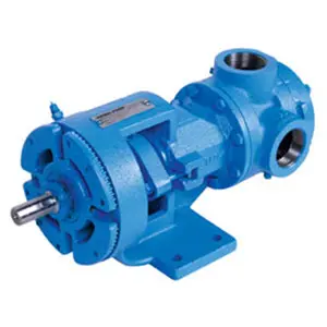
Viking Pump AS4197
Need answers fast?
Explore the manual using AI.

Turn manuals into instant answers
with your AI-powered assistantTurn manuals into instant answers
with your AI-powered assistant
Manual for Viking Pump AS4197
Complete asset maintenance, one click away
Get instant access to all the maintenance information you need. Empower technicians to perform preventive maintenance with asset packages, ready to use right out of the box.

Documents & Manuals
Find all the essential guides in one place.
 Tensioning Guide
- Belt-diagram
- C-120 pulleys
+ 13 more

Work Order Templates
Pre-built workflows to keep your asset running smoothly.
- Daily Electrical System Inspection
- Replace Roller and Pulley
- Install Engine B-120
+ 29 more

Procedures
Integrate maintenance plans directly into your work orders.
- Motion Industries
- Applied Industrial Technologies
- Electrical Brothers
+ 5 more

Parts
Access the parts list for your equipment in MaintainX.
- Drive Motor
- B2 Rollers
- Tensioning System
+ 40 more
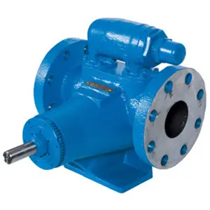
Viking Pump AS4197
Create an account to install this asset package.
Maintenance Plans for Viking Pump Model AS4197
Integrate maintenance plans directly into your work orders in MaintainX.
Carbon Graphite Bushings Installation
Danger! Before opening any Viking pump liquid chamber (pumping chamber, reservoir, relief valve adjusting cap fitting, etc.) be sure:
Pressure in the chamber has been completely vented through the suction or discharge lines, or other appropriate openings or connections.
The driving means (motor, turbine, engine, etc.) has been “locked out” or made non-operational, so that it cannot be started while work is being done on pump.
You know what liquid the pump has been handling and the precautions necessary to safely handle the liquid. Obtain a material safety data sheet (MSDS) for the liquid to be sure these precautions are understood.
Failure to follow above listed precautionary measures may result in serious injury or death.
When installing graphite bushings, extreme care must be taken to prevent breaking. Carbon graphite is a brittle material and easily cracked. If cracked the bushing will quickly disintegrate. Using a lubricant and adding a chamfer on the bushing and the mating part will help in installation.
A press was used for installation.
Bushing was started straight.
Did not stop pressing operation until bushing is in proper position, starting and stopping will result in cracked bushing.

Trust Bearing Adjustment
Danger! Before opening any Viking pump liquid chamber (pumping chamber, reservoir, relief valve adjusting cap fitting, etc.) be sure:
Pressure in the chamber has been completely vented through the suction or discharge lines, or other appropriate openings or connections.
The driving means (motor, turbine, engine, etc.) has been “locked out” or made non-operational, so that it cannot be started while work is being done on pump.
You know what liquid the pump has been handling and the precautions necessary to safely handle the liquid. Obtain a material safety data sheet (MSDS) for the liquid to be sure these precautions are understood.
Failure to follow above listed precautionary measures may result in serious injury or death.
Loosen two screws in face of thrust bearing assembly.
If shaft cannot be rotated freely, turn thrust bearing assembly counter clockwise until shaft cannot be turned easily.
To set end clearance:
While turning rotor shaft, rotate thrust bearing assembly clockwise until noticeable drag occurs (this is zero end clearance).
Pressure Relief Valve Pressure Adjustment
Danger! Before opening any Viking pump liquid chamber (pumping chamber, reservoir, relief valve adjusting cap fitting, etc.) be sure:
Pressure in the chamber has been completely vented through the suction or discharge lines, or other appropriate openings or connections.
The driving means (motor, turbine, engine, etc.) has been “locked out” or made non-operational, so that it cannot be started while work is being done on pump.
You know what liquid the pump has been handling and the precautions necessary to safely handle the liquid. Obtain a material safety data sheet (MSDS) for the liquid to be sure these precautions are understood.
PRESSURE ADJUSTMENT If a new spring is installed or if pressure setting of pressure relief valve is to be changed from that which the factory has set, the following instructions must be carefully followed.
Carefully remove valve cap, which covers adjusting screw. Loosen locknut, which locks adjusting screw so pressure setting will not change during operation of pump.
Install pressure gauge in discharge line for actual adjustment operation.
Turn adjusting screw to increase pressure and out to decrease pressure.
With discharge line closed at a point beyond pressure gauge, gauge will show maximum pressure valve will allow while pump is in operation.
Pump Cleaning
Warning: Ensure the pump is turned off and disconnected from power source before cleaning.
Is the pump disconnected from power source?
Is the pump clean?
Upload a photo of the cleaned pump
Sign off on the pump cleaning
Parts for Viking Pump AS4197
Access the parts list for your equipment in MaintainX.
Mechanical Seal Installation Sleeve for 1¼ Inch Seal;
2-810-004-900
Mechanical Seal Installation Sleeve for 1¼ Inch Seal;
2-810-004-900
Mechanical Seal Installation Sleeve for 1¼ Inch Seal;
2-810-004-900
Unlock efficiency
with MaintainX CoPilot
MaintainX CoPilot is your expert colleague, on call 24/7, helping your team find the answers they need to keep equipment running.
Reduce Unplanned Downtime
Ensure your team follows consistent procedures to minimize equipment failures and costly delays.
Maximize Asset Availability
Keep your assets running longer and more reliably, with standardized maintenance workflows from OEM manuals.
Lower Maintenance Costs
Turn any technician into an expert to streamline operations, maintain more assets, and reduce overall costs.
Thousands of companies manage their assets with MaintainX

'%3e%3cpath%20fill='url(%23b)'%20d='M66.008%2080.068c-5.084-.786-9.763-3.834-12.442-8.68a16.942%2016.942%200%200%201-1.87-5.18c1.096.19%202.203.476%203.298.87%206.525%202.333%2010.836%207.68%2011.014%2012.99ZM51.47%2061.576c.488-5.524%203.62-10.716%208.847-13.597a17.132%2017.132%200%200%201%2011.335-1.882c-.798%208.145-7.43%2014.848-16.038%2015.599-1.417.119-2.799.07-4.144-.12Zm28.564-11.478a17.513%2017.513%200%200%201%203.727%204.62c4.608%208.335%201.584%2018.813-6.75%2023.409a16.988%2016.988%200%200%201-4.359%201.679%2019.624%2019.624%200%200%201-3.977-12.776c.346-7.561%204.942-13.931%2011.36-16.932Z'/%3e%3cpath%20fill='%23110F0D'%20fill-rule='evenodd'%20d='M142.831%2048.324h4.977V77.03h-4.977V48.324Zm27.278%2013.002c.322%201.048.453%202.263.453%203.62v12.073h-4.787V66.208c0-.75-.047-1.572-.154-2.143-.453-2.382-1.822-3.572-4.215-3.572-2.31%200-3.882%201.274-4.43%203.476-.143.596-.226%201.405-.226%202.25v10.8h-4.787V56.623h4.477v2.989c1.536-2.5%203.906-3.43%206.371-3.43%203.488%200%206.263%201.68%207.298%205.144Zm24.636%207.323c0%203.882-2.358%206.525-5.763%207.727-1.298.453-2.632.643-4.62.643h-10.169V48.324h9.085c1.691%200%203.156.143%204.049.38%203.465.93%205.727%203.68%205.727%207.335%200%202.441-.81%204.156-2.762%205.644%202.905%201.417%204.453%203.727%204.453%206.966Zm-15.634-8.656h4.584c1.024%200%201.917-.143%202.536-.417%201.215-.548%201.905-1.608%201.905-3.167%200-1.548-.643-2.572-1.845-3.132-.691-.31-1.762-.452-2.763-.452h-4.417v7.168Zm10.716%208.465c0-1.536-.893-3.37-3.227-3.893-.428-.095-1.036-.143-1.571-.143h-5.918v8.085h5.501c.56%200%201.429-.048%201.953-.167%201.94-.453%203.262-1.846%203.262-3.882Zm47.747-11.847-8.097%2020.408h-4.429l-8.109-20.408h5.191l5.192%2014.574%205.108-14.574h5.144Zm-20.218%2010.002c0%20.69-.036%201.262-.155%201.94h-15.943c.631%202.87%202.714%204.728%205.882%204.728%202.131%200%203.607-.882%204.703-2.525h4.87c-1.762%204.144-5.204%206.692-9.657%206.692-6.084%200-10.537-4.858-10.537-10.49%200-6.108%204.524-10.776%2010.335-10.776%206.239%200%2010.442%204.954%2010.502%2010.43Zm-4.763-1.405c-.333-2.846-2.643-4.858-5.691-4.858-2.894%200-5.287%201.929-5.621%204.858h11.312Zm-72.667%203.44c0%204.787-3.287%208.371-9.419%208.371H119.363V64.66c-1.917.274-3.87.69-5.811%201.238l4.537%2011.121h-5.418l-3.596-9.585c-5.144%202.084-10.085%205.216-14.217%209.585h-4.786L101.8%2048.312h4.56l5.68%2013.883a44.112%2044.112%200%200%201%207.323-1.774V48.312h9.084c1.703%200%203.156.143%204.061.393%203.453.929%205.727%203.667%205.727%207.323%200%201.917-.738%204.179-2.81%205.691%203.06%201.56%204.501%204.025%204.501%206.93Zm-15.634-8.667a62.664%2062.664%200%200%201%202.06-.036c1.703.012%203.239.131%204.608.37%201.441-.549%202.357-1.727%202.357-3.537%200-1.941-.881-3.144-2.488-3.667-.548-.18-1.358-.286-2.322-.286h-4.215v7.156Zm-16.55%203.905-3.715-9.894-6.394%2016.502c2.833-2.595%206.263-4.858%2010.109-6.608Zm27.254%204.74c0-2.775-3.131-4.347-8.513-4.418-.715%200-1.441.011-2.191.047v8.252h5.918c2.548%200%204.786-1.37%204.786-3.882Z'%20clip-rule='evenodd'/%3e%3c/g%3e%3cdefs%3e%3clinearGradient%20id='b'%20x1='51.47'%20x2='85.916'%20y1='62.946'%20y2='62.946'%20gradientUnits='userSpaceOnUse'%3e%3cstop%20stop-color='%23CD9F28'/%3e%3cstop%20offset='1'%20stop-color='%23ECD80B'/%3e%3c/linearGradient%3e%3cclipPath%20id='a'%3e%3cpath%20fill='%23fff'%20d='M51.47%2045.728h186.104V80.14H51.47z'/%3e%3c/clipPath%3e%3c/defs%3e%3c/svg%3e)


More from Viking

Explore Other Assets


© 2026 MaintainX. All rights reserved.