


'%3e%3cpath%20d='M10%2010.5V17h12.5v5.5l-21%20.038V15l8.5-4.5ZM1%206h11M6.5%202H12M5.5%2022.5V19'/%3e%3cpath%20d='M21.21%2017.012%2020.14%201.5h-4.28l-1.07%2015.512M15.516%206.49h4.967'/%3e%3c/g%3e%3cdefs%3e%3cclipPath%20id='a'%3e%3cpath%20fill='%23fff'%20d='M0%200h24v24H0z'/%3e%3c/clipPath%3e%3c/defs%3e%3c/svg%3e)











Hyster-Yale Forklift H50CT
Need answers fast?
Explore the manual using AI.
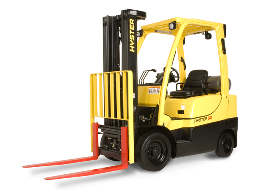
The Hyster-Yale H50CT is a robust forklift designed for industrial applications, offering exceptional lifting capabilities and maneuverability. This model is ideal for warehouses and distribution centers, ensuring efficient material handling and productivity. With its durable construction and reliable performance, the H50CT is a trusted choice for various lifting tasks.
Turn manuals into instant answers
with your AI-powered assistantTurn manuals into instant answers
with your AI-powered assistant
Manual for Hyster-Yale Forklift H50CT
Complete asset maintenance, one click away
Get instant access to all the maintenance information you need. Empower technicians to perform preventive maintenance with asset packages, ready to use right out of the box.

Documents & Manuals
Find all the essential guides in one place.
 Tensioning Guide
- Belt-diagram
- C-120 pulleys
+ 13 more

Work Order Templates
Pre-built workflows to keep your asset running smoothly.
- Daily Electrical System Inspection
- Replace Roller and Pulley
- Install Engine B-120
+ 29 more

Procedures
Integrate maintenance plans directly into your work orders.
- Motion Industries
- Applied Industrial Technologies
- Electrical Brothers
+ 5 more

Parts
Access the parts list for your equipment in MaintainX.
- Drive Motor
- B2 Rollers
- Tensioning System
+ 40 more
Hyster-Yale Forklift H50CT
Create an account to install this asset package.
Maintenance Plans for Hyster-Yale Forklift Model H50CT
Integrate maintenance plans directly into your work orders in MaintainX.
Battery Replacement
REMOVE
1. Raise the hood. Disconnect the battery.
2. Remove battery lockdown bar from battery. Remove battery from lift truck. See Figure 29.
INSTALL
1. Install new battery onto battery tray. Install battery lockdown bar onto battery. See Figure 29.
2. Connect the battery. Close the hood.;

Direction Control Lever Replacement
NOTE: The direction control lever is located on left side of Display Switch Cluster. The direction control lever is non-repairable and must be replaced as an assembly. See the Parts Manual for replacement part number.
Insert two small, flat-blade or Phillips screwdrivers, with a 3.175 mm (0.125 in.) or less, wide blade or die end, into the opening on the Display Switch Cluster on an outward angle enough to compress the spring tab on the direction control lever.
Pry the spring tab toward the body of the direction control lever or turn signal lever and, at the same time, pull on the handle of the lever enough to free the tab of the interior lock of the Display Switch Cluster.
Repeat the previous steps on the opposite side of the direction control lever. Remove the direction control lever from the Display Switch Cluster.
Install the direction control lever into the opening of the Display Switch Cluster until the locking tabs are engaged in the Display Switch Cluster.
Sign off on the direction control lever replacement
Display Switch Cluster Panel Bezel And Overlay Replacement
Removal
Insert a small, flat-bladed screwdriver into the top slot on the inner edge of the bezel and pry outward
Repeat procedure at the lower slot on the bezel
Lift bezel off of Display Switch Cluster
Remove overlay from Display Switch Cluster
Installation
Place new overlay on display panel
Install a new bezel by inserting the outer edge in the display
Press down the inner edge
Display Switch Cluster Replacement
NOTE: The Display Switch Cluster is a non-repairable part. See Parts Manual for replacement part number.
Disconnect ground wire
Lift up on the steering wheel slightly and pull up on the tilt lever. Fully lower the steering column.
Remove upper steering column cover by pulling up on upper steering column cover to release the latches (one on either side), and pulling cover away from steering column.
Remove the horn button and disconnect the horn wires.
NOTE: A puller tool may be required to remove the steering wheel.
Remove the lock nut securing the steering wheel and remove steering wheel from steering column. Take care to not damage the horn wires.
Disconnect the Display Switch Cluster harness from the Display Switch Cluster. Remove the four bolts securing the Display Switch Cluster. Slide the display panel off of the steering column.
Install Display Switch Cluster onto steering column. Install four bolts to secure panel to steering column and tighten bolts to 19 N•m (168 lbf in).
Key Switch Replacement
Remove
1. Fully lower the steering column and remove the upper steering column cover by pushing in on both sides of the cover to release the latches (one on either side), and pulling cover away from steering column. See Figure 3.
2. Remove torx head capscrews. See Figure 7.
3. Slide key switch assembly out of Display Switch Cluster. See Figure 7.
Install
1. Install new key switch assembly into Display Switch Cluster. Install torx head capscrews (T-15) to secure key switch to Display Switch Cluster. Tighten torx head capscrews to 1.1 N•m (9.7 lbf in). See Figure 7.
2. Install upper steering cover on steering column. Align latches on upper steering cover to holes on steering column and push upper steering cover into place on steering column.;
Unlock efficiency
with MaintainX CoPilot
MaintainX CoPilot is your expert colleague, on call 24/7, helping your team find the answers they need to keep equipment running.
'%20stroke-width='2.05034'/%3e%3cpath%20d='M43.601%2020.8897C43.2688%2019.252%2042.7312%2017.6627%2042.001%2016.1597'%20stroke='url(%23paint1_linear_4912_14668)'%20stroke-width='2.05034'/%3e%3cpath%20d='M40.001%2012.8882C38.8627%2011.3731%2037.516%2010.0265%2036.001%208.88818'%20stroke='url(%23paint2_linear_4912_14668)'%20stroke-width='2.05034'/%3e%3cpath%20d='M32.729%206.89053C31.2266%206.1604%2029.638%205.62282%2028.001%205.29053'%20stroke='url(%23paint3_linear_4912_14668)'%20stroke-width='2.05034'/%3e%3cpath%20d='M24.001%2014.8901V24.8901L32.001%2032.8901'%20stroke='url(%23paint4_linear_4912_14668)'%20stroke-width='2.05034'/%3e%3cdefs%3e%3clinearGradient%20id='paint0_linear_4912_14668'%20x1='4'%20y1='25'%20x2='44'%20y2='25'%20gradientUnits='userSpaceOnUse'%3e%3cstop%20stop-color='%23246CFF'/%3e%3cstop%20offset='1'%20stop-color='%232ED888'/%3e%3c/linearGradient%3e%3clinearGradient%20id='paint1_linear_4912_14668'%20x1='3.5'%20y1='20.8897'%20x2='44'%20y2='20.8897'%20gradientUnits='userSpaceOnUse'%3e%3cstop%20stop-color='%23246CFF'/%3e%3cstop%20offset='1'%20stop-color='%232ED888'/%3e%3c/linearGradient%3e%3clinearGradient%20id='paint2_linear_4912_14668'%20x1='3.5'%20y1='12.8882'%20x2='44.5'%20y2='12.8882'%20gradientUnits='userSpaceOnUse'%3e%3cstop%20stop-color='%23246CFF'/%3e%3cstop%20offset='1'%20stop-color='%232ED888'/%3e%3c/linearGradient%3e%3clinearGradient%20id='paint3_linear_4912_14668'%20x1='6.5'%20y1='6.89053'%20x2='43.5'%20y2='6.89053'%20gradientUnits='userSpaceOnUse'%3e%3cstop%20stop-color='%23246CFF'/%3e%3cstop%20offset='1'%20stop-color='%232ED888'/%3e%3c/linearGradient%3e%3clinearGradient%20id='paint4_linear_4912_14668'%20x1='5'%20y1='32.8901'%20x2='44'%20y2='32.8901'%20gradientUnits='userSpaceOnUse'%3e%3cstop%20stop-color='%23246CFF'/%3e%3cstop%20offset='1'%20stop-color='%232ED888'/%3e%3c/linearGradient%3e%3c/defs%3e%3c/svg%3e)
Reduce Unplanned Downtime
Ensure your team follows consistent procedures to minimize equipment failures and costly delays.
'%20stroke-width='2.05034'/%3e%3cpath%20d='M46.667%2041.7231C46.667%2044.5079%2045.5607%2047.1786%2043.5916%2049.1478C41.6225%2051.1169%2038.9518%2052.2231%2036.167%2052.2231C33.3822%2052.2231%2030.7115%2051.1169%2028.7424%2049.1478C26.7732%2047.1786%2025.667%2044.5079%2025.667%2041.7231C25.667%2038.9384%2026.7732%2036.2677%2028.7424%2034.2985C30.7115%2032.3294%2033.3822%2031.2231%2036.167%2031.2231C38.9518%2031.2231%2041.6225%2032.3294%2043.5916%2034.2985C45.5607%2036.2677%2046.667%2038.9384%2046.667%2041.7231Z'%20stroke='url(%23paint1_linear_4912_14680)'%20stroke-width='2.05034'/%3e%3cpath%20d='M37.334%2035.8896V40.5563H42.0007'%20stroke='url(%23paint2_linear_4912_14680)'%20stroke-width='2.05034'/%3e%3cdefs%3e%3clinearGradient%20id='paint0_linear_4912_14680'%20x1='5'%20y1='52.2231'%20x2='51'%20y2='52.2231'%20gradientUnits='userSpaceOnUse'%3e%3cstop%20stop-color='%23246CFF'/%3e%3cstop%20offset='1'%20stop-color='%232ED888'/%3e%3c/linearGradient%3e%3clinearGradient%20id='paint1_linear_4912_14680'%20x1='5'%20y1='52.2231'%20x2='47'%20y2='52.2231'%20gradientUnits='userSpaceOnUse'%3e%3cstop%20stop-color='%23246CFF'/%3e%3cstop%20offset='1'%20stop-color='%232ED888'/%3e%3c/linearGradient%3e%3clinearGradient%20id='paint2_linear_4912_14680'%20x1='5'%20y1='40.5563'%20x2='52.5'%20y2='40.5563'%20gradientUnits='userSpaceOnUse'%3e%3cstop%20stop-color='%23246CFF'/%3e%3cstop%20offset='1'%20stop-color='%232ED888'/%3e%3c/linearGradient%3e%3c/defs%3e%3c/svg%3e)
Maximize Asset Availability
Keep your assets running longer and more reliably, with standardized maintenance workflows from OEM manuals.
'%20stroke-width='2.05034'/%3e%3cpath%20d='M13.9995%2024.2231C13.9995%2029.1738%2015.9662%2033.9217%2019.4669%2037.4224C22.9675%2040.9231%2027.7155%2042.8897%2032.6662%2042.8897C37.6169%2042.8897%2042.3648%2040.9231%2045.8655%2037.4224C49.3662%2033.9217%2051.3328%2029.1738%2051.3328%2024.2231C51.3328%2019.2724%2049.3662%2014.5244%2045.8655%2011.0237C42.3648%207.52306%2037.6169%205.5564%2032.6662%205.5564C27.7155%205.5564%2022.9675%207.52306%2019.4669%2011.0237C15.9662%2014.5244%2013.9995%2019.2724%2013.9995%2024.2231Z'%20stroke='url(%23paint1_linear_4912_14674)'%20stroke-width='2.05034'/%3e%3cpath%20d='M32.6665%2017.2231V12.5564'%20stroke='url(%23paint2_linear_4912_14674)'%20stroke-width='2.05034'/%3e%3cpath%20d='M32.6665%2035.8898V31.2231'%20stroke='url(%23paint3_linear_4912_14674)'%20stroke-width='2.05034'/%3e%3cpath%20d='M37.9165%2020.7231V19.5565C37.9165%2018.9376%2037.6707%2018.3441%2037.2331%2017.9066C36.7955%2017.469%2036.202%2017.2231%2035.5832%2017.2231H29.7498C29.131%2017.2231%2028.5375%2017.469%2028.0999%2017.9066C27.6623%2018.3441%2027.4165%2018.9376%2027.4165%2019.5565V20.6018C27.4166%2021.1326%2027.5977%2021.6475%2027.9298%2022.0615C28.262%2022.4756%2028.7254%2022.764%2029.2435%2022.8791L36.0895%2024.4005C36.6077%2024.5157%2037.071%2024.8041%2037.4032%2025.2181C37.7353%2025.6321%2037.9164%2026.147%2037.9165%2026.6778V28.8898C37.9165%2029.5086%2037.6707%2030.1021%2037.2331%2030.5397C36.7955%2030.9773%2036.202%2031.2231%2035.5832%2031.2231H29.7498C29.131%2031.2231%2028.5375%2030.9773%2028.0999%2030.5397C27.6623%2030.1021%2027.4165%2029.5086%2027.4165%2028.8898V27.7231'%20stroke='url(%23paint4_linear_4912_14674)'%20stroke-width='2.05034'/%3e%3cdefs%3e%3clinearGradient%20id='paint0_linear_4912_14674'%20x1='5'%20y1='33.5'%20x2='50'%20y2='33.5'%20gradientUnits='userSpaceOnUse'%3e%3cstop%20stop-color='%23246CFF'/%3e%3cstop%20offset='1'%20stop-color='%232ED888'/%3e%3c/linearGradient%3e%3clinearGradient%20id='paint1_linear_4912_14674'%20x1='5'%20y1='42.8897'%20x2='48.5'%20y2='42.8897'%20gradientUnits='userSpaceOnUse'%3e%3cstop%20stop-color='%23246CFF'/%3e%3cstop%20offset='1'%20stop-color='%232ED888'/%3e%3c/linearGradient%3e%3clinearGradient%20id='paint2_linear_4912_14674'%20x1='5'%20y1='17.2231'%20x2='52.5'%20y2='17.2231'%20gradientUnits='userSpaceOnUse'%3e%3cstop%20stop-color='%23246CFF'/%3e%3cstop%20offset='1'%20stop-color='%232ED888'/%3e%3c/linearGradient%3e%3clinearGradient%20id='paint3_linear_4912_14674'%20x1='3.5'%20y1='35.8898'%20x2='50.5'%20y2='35.8898'%20gradientUnits='userSpaceOnUse'%3e%3cstop%20stop-color='%23246CFF'/%3e%3cstop%20offset='1'%20stop-color='%232ED888'/%3e%3c/linearGradient%3e%3clinearGradient%20id='paint4_linear_4912_14674'%20x1='3'%20y1='31.2231'%20x2='52'%20y2='31.2231'%20gradientUnits='userSpaceOnUse'%3e%3cstop%20stop-color='%23246CFF'/%3e%3cstop%20offset='1'%20stop-color='%232ED888'/%3e%3c/linearGradient%3e%3c/defs%3e%3c/svg%3e)
Lower Maintenance Costs
Turn any technician into an expert to streamline operations, maintain more assets, and reduce overall costs.
Thousands of companies manage their assets with MaintainX

'%3e%3cpath%20fill='url(%23b)'%20d='M66.008%2080.068c-5.084-.786-9.763-3.834-12.442-8.68a16.942%2016.942%200%200%201-1.87-5.18c1.096.19%202.203.476%203.298.87%206.525%202.333%2010.836%207.68%2011.014%2012.99ZM51.47%2061.576c.488-5.524%203.62-10.716%208.847-13.597a17.132%2017.132%200%200%201%2011.335-1.882c-.798%208.145-7.43%2014.848-16.038%2015.599-1.417.119-2.799.07-4.144-.12Zm28.564-11.478a17.513%2017.513%200%200%201%203.727%204.62c4.608%208.335%201.584%2018.813-6.75%2023.409a16.988%2016.988%200%200%201-4.359%201.679%2019.624%2019.624%200%200%201-3.977-12.776c.346-7.561%204.942-13.931%2011.36-16.932Z'/%3e%3cpath%20fill='%23110F0D'%20fill-rule='evenodd'%20d='M142.831%2048.324h4.977V77.03h-4.977V48.324Zm27.278%2013.002c.322%201.048.453%202.263.453%203.62v12.073h-4.787V66.208c0-.75-.047-1.572-.154-2.143-.453-2.382-1.822-3.572-4.215-3.572-2.31%200-3.882%201.274-4.43%203.476-.143.596-.226%201.405-.226%202.25v10.8h-4.787V56.623h4.477v2.989c1.536-2.5%203.906-3.43%206.371-3.43%203.488%200%206.263%201.68%207.298%205.144Zm24.636%207.323c0%203.882-2.358%206.525-5.763%207.727-1.298.453-2.632.643-4.62.643h-10.169V48.324h9.085c1.691%200%203.156.143%204.049.38%203.465.93%205.727%203.68%205.727%207.335%200%202.441-.81%204.156-2.762%205.644%202.905%201.417%204.453%203.727%204.453%206.966Zm-15.634-8.656h4.584c1.024%200%201.917-.143%202.536-.417%201.215-.548%201.905-1.608%201.905-3.167%200-1.548-.643-2.572-1.845-3.132-.691-.31-1.762-.452-2.763-.452h-4.417v7.168Zm10.716%208.465c0-1.536-.893-3.37-3.227-3.893-.428-.095-1.036-.143-1.571-.143h-5.918v8.085h5.501c.56%200%201.429-.048%201.953-.167%201.94-.453%203.262-1.846%203.262-3.882Zm47.747-11.847-8.097%2020.408h-4.429l-8.109-20.408h5.191l5.192%2014.574%205.108-14.574h5.144Zm-20.218%2010.002c0%20.69-.036%201.262-.155%201.94h-15.943c.631%202.87%202.714%204.728%205.882%204.728%202.131%200%203.607-.882%204.703-2.525h4.87c-1.762%204.144-5.204%206.692-9.657%206.692-6.084%200-10.537-4.858-10.537-10.49%200-6.108%204.524-10.776%2010.335-10.776%206.239%200%2010.442%204.954%2010.502%2010.43Zm-4.763-1.405c-.333-2.846-2.643-4.858-5.691-4.858-2.894%200-5.287%201.929-5.621%204.858h11.312Zm-72.667%203.44c0%204.787-3.287%208.371-9.419%208.371H119.363V64.66c-1.917.274-3.87.69-5.811%201.238l4.537%2011.121h-5.418l-3.596-9.585c-5.144%202.084-10.085%205.216-14.217%209.585h-4.786L101.8%2048.312h4.56l5.68%2013.883a44.112%2044.112%200%200%201%207.323-1.774V48.312h9.084c1.703%200%203.156.143%204.061.393%203.453.929%205.727%203.667%205.727%207.323%200%201.917-.738%204.179-2.81%205.691%203.06%201.56%204.501%204.025%204.501%206.93Zm-15.634-8.667a62.664%2062.664%200%200%201%202.06-.036c1.703.012%203.239.131%204.608.37%201.441-.549%202.357-1.727%202.357-3.537%200-1.941-.881-3.144-2.488-3.667-.548-.18-1.358-.286-2.322-.286h-4.215v7.156Zm-16.55%203.905-3.715-9.894-6.394%2016.502c2.833-2.595%206.263-4.858%2010.109-6.608Zm27.254%204.74c0-2.775-3.131-4.347-8.513-4.418-.715%200-1.441.011-2.191.047v8.252h5.918c2.548%200%204.786-1.37%204.786-3.882Z'%20clip-rule='evenodd'/%3e%3c/g%3e%3cdefs%3e%3clinearGradient%20id='b'%20x1='51.47'%20x2='85.916'%20y1='62.946'%20y2='62.946'%20gradientUnits='userSpaceOnUse'%3e%3cstop%20stop-color='%23CD9F28'/%3e%3cstop%20offset='1'%20stop-color='%23ECD80B'/%3e%3c/linearGradient%3e%3cclipPath%20id='a'%3e%3cpath%20fill='%23fff'%20d='M51.47%2045.728h186.104V80.14H51.47z'/%3e%3c/clipPath%3e%3c/defs%3e%3c/svg%3e)











More from Hyster-Yale

Explore Other Assets









© 2026 MaintainX. All rights reserved.