


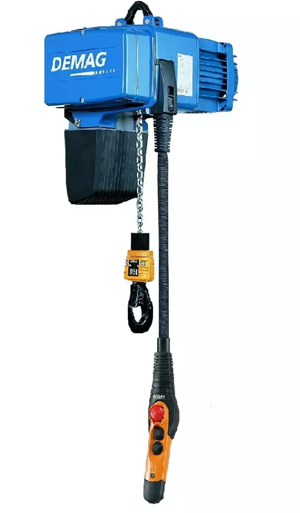
DEMAG Electric Chain Hoist Demag DC-COM 2 250 1/1 H5 V7.2/1.8
Need answers fast?
Explore the manual using AI.

Turn manuals into instant answers
with your AI-powered assistantTurn manuals into instant answers
with your AI-powered assistant
Manual for DEMAG Electric Chain Hoist Demag DC-COM 2 250 1/1 H5 V7.2/1.8
Complete asset maintenance, one click away
Get instant access to all the maintenance information you need. Empower technicians to perform preventive maintenance with asset packages, ready to use right out of the box.

Documents & Manuals
Find all the essential guides in one place.
 Tensioning Guide
- Belt-diagram
- C-120 pulleys
+ 13 more

Work Order Templates
Pre-built workflows to keep your asset running smoothly.
- Daily Electrical System Inspection
- Replace Roller and Pulley
- Install Engine B-120
+ 29 more

Procedures
Integrate maintenance plans directly into your work orders.
- Motion Industries
- Applied Industrial Technologies
- Electrical Brothers
+ 5 more

Parts
Access the parts list for your equipment in MaintainX.
- Drive Motor
- B2 Rollers
- Tensioning System
+ 40 more
DEMAG Electric Chain Hoist Demag DC-COM 2 250 1/1 H5 V7.2/1.8
Create an account to install this asset package.
Maintenance Plans for DEMAG Electric Chain Hoist Model Demag DC-COM 2 250 1/1 H5 V7.2/1.8
Integrate maintenance plans directly into your work orders in MaintainX.
Bottom Block Standard Replacement
Remove guide half sections (1) (four M 6 bolts)
Remove bottom block retaining bolts (2) and remove the bottom block
Insert the new chain into the bottom block in the same position and orientation (chain must operate without any twist)
Re-assemble the bottom block and tighten bolts (2) to a torque of 52 Nm
Check correct fit of the four cut-off springs (3) in new halves (4) of the bottom block
Install new guide half sections (1) and tighten bolts (5) to a torque of 5,5 Nm
Apply the load capacity plate
Perform a function check (run against the operating limit switches and check against the 7-segment display)
Sign off on the bottom block standard replacement

10 Yearly Brake Wear Check
Check brake wear
Check brake wear depending on the year of manufacture of your chain hoist:
● When the max. brake displacement is reached (see Tab. 64, Page 88), the brake must be replaced immediately.
● For brake displacement up to 0,5 mm, the brake can still be used until the next maintenance is due.
As of year of manufacture 04/2009
Since 04/2009 – depending on the size of model – brakes have been gradually equipped with a plug inside the brake housing to enable brake wear to be measured without the need to remove the brake. Brake wear is measured by the air gap.
Disconnect the chain hoist from the power supply (mains connection switch) and secure it against switching on again.
● Open the electric equipment cover.
● Unscrew brake plug screw (1) from the brake.
10 Yearly Oil Change
Dispose of waste oil in accordance with environmental protection requirements.
Under normal operating conditions, the lubricant must be changed at least every 10 years.
Under exceptional conditions, e.g. increased ambient temperatures, we recommend that oil changes be adapted to suit these conditions.
Enter the type of oil used
CAUTION: Safe operation cannot be ensured if oils are used that are not approved.
Drain the old oil at operating temperature.
Turn the gearbox in such a way that the oil is drained.
The flushing oil should have a viscosity of 46-68 mm2/s at rated temperature.
Enter the quantity of flushing oil used
Contactor On Control Board Replacement
Warning: Ensure the power is off before starting the procedure
Unclip the contactor retaining mechanism by pressing locking tab (A) with your thumb. This carefully bends locking tab (A) away from the contactor.
Turn contactor (B) using your other hand until the mechanism no longer holds it.
Unclip second locking tab (A) on the opposite side (as described in step 1 above).
Using your other hand, remove contactor (B) by pulling it away from the board.
Push the replacement contactor into contactor socket (C) until both locking tabs (A) click into position.
Note: The contactors are also socket-mounted for sizes DC 1 to 5 manufactured as of 02/2011 and can be individually replaced.
Sign off on the contactor replacement
Control Cable Replacement
DANGER: Live components. Danger to life and limb. Work on the electric equipment may only be carried out by a qualified electrician or by trained personnel.
Disconnect the chain hoist from the power supply (mains connection switch) and secure it against switching on again.
Open and disconnect the service cover.
Remove and open bag (1) with the control cable.
Take the control cable out of the bag.
Turn and disconnect bayonet lock (2) and remove the control cable plug connector.
Unscrew electric equipment cover.
Loosen screw (3) on the control cable locking mechanism and remove the locking mechanism. Remove the control cable.
Install the new control cable in reverse order.
Parts for DEMAG Electric Chain Hoist Demag DC-COM 2 250 1/1 H5 V7.2/1.8
Access the parts list for your equipment in MaintainX.
Cross-Travel Limit Switch
716 663 45
Relevant Operating Regulations
214 748 44
Guide Plate Accessories
717 830 45
Chain Gauge
836 025 44
Gear Grease
665 009 44
Cross-Travel Limit Switch
716 663 45
Relevant Operating Regulations
214 748 44
Guide Plate Accessories
717 830 45
Chain Gauge
836 025 44
Gear Grease
665 009 44
Cross-Travel Limit Switch
716 663 45
Relevant Operating Regulations
214 748 44
Guide Plate Accessories
717 830 45
Chain Gauge
836 025 44
Gear Grease
665 009 44
Unlock efficiency
with MaintainX CoPilot
MaintainX CoPilot is your expert colleague, on call 24/7, helping your team find the answers they need to keep equipment running.
Reduce Unplanned Downtime
Ensure your team follows consistent procedures to minimize equipment failures and costly delays.
Maximize Asset Availability
Keep your assets running longer and more reliably, with standardized maintenance workflows from OEM manuals.
Lower Maintenance Costs
Turn any technician into an expert to streamline operations, maintain more assets, and reduce overall costs.
Thousands of companies manage their assets with MaintainX

'%3e%3cpath%20fill='url(%23b)'%20d='M66.008%2080.068c-5.084-.786-9.763-3.834-12.442-8.68a16.942%2016.942%200%200%201-1.87-5.18c1.096.19%202.203.476%203.298.87%206.525%202.333%2010.836%207.68%2011.014%2012.99ZM51.47%2061.576c.488-5.524%203.62-10.716%208.847-13.597a17.132%2017.132%200%200%201%2011.335-1.882c-.798%208.145-7.43%2014.848-16.038%2015.599-1.417.119-2.799.07-4.144-.12Zm28.564-11.478a17.513%2017.513%200%200%201%203.727%204.62c4.608%208.335%201.584%2018.813-6.75%2023.409a16.988%2016.988%200%200%201-4.359%201.679%2019.624%2019.624%200%200%201-3.977-12.776c.346-7.561%204.942-13.931%2011.36-16.932Z'/%3e%3cpath%20fill='%23110F0D'%20fill-rule='evenodd'%20d='M142.831%2048.324h4.977V77.03h-4.977V48.324Zm27.278%2013.002c.322%201.048.453%202.263.453%203.62v12.073h-4.787V66.208c0-.75-.047-1.572-.154-2.143-.453-2.382-1.822-3.572-4.215-3.572-2.31%200-3.882%201.274-4.43%203.476-.143.596-.226%201.405-.226%202.25v10.8h-4.787V56.623h4.477v2.989c1.536-2.5%203.906-3.43%206.371-3.43%203.488%200%206.263%201.68%207.298%205.144Zm24.636%207.323c0%203.882-2.358%206.525-5.763%207.727-1.298.453-2.632.643-4.62.643h-10.169V48.324h9.085c1.691%200%203.156.143%204.049.38%203.465.93%205.727%203.68%205.727%207.335%200%202.441-.81%204.156-2.762%205.644%202.905%201.417%204.453%203.727%204.453%206.966Zm-15.634-8.656h4.584c1.024%200%201.917-.143%202.536-.417%201.215-.548%201.905-1.608%201.905-3.167%200-1.548-.643-2.572-1.845-3.132-.691-.31-1.762-.452-2.763-.452h-4.417v7.168Zm10.716%208.465c0-1.536-.893-3.37-3.227-3.893-.428-.095-1.036-.143-1.571-.143h-5.918v8.085h5.501c.56%200%201.429-.048%201.953-.167%201.94-.453%203.262-1.846%203.262-3.882Zm47.747-11.847-8.097%2020.408h-4.429l-8.109-20.408h5.191l5.192%2014.574%205.108-14.574h5.144Zm-20.218%2010.002c0%20.69-.036%201.262-.155%201.94h-15.943c.631%202.87%202.714%204.728%205.882%204.728%202.131%200%203.607-.882%204.703-2.525h4.87c-1.762%204.144-5.204%206.692-9.657%206.692-6.084%200-10.537-4.858-10.537-10.49%200-6.108%204.524-10.776%2010.335-10.776%206.239%200%2010.442%204.954%2010.502%2010.43Zm-4.763-1.405c-.333-2.846-2.643-4.858-5.691-4.858-2.894%200-5.287%201.929-5.621%204.858h11.312Zm-72.667%203.44c0%204.787-3.287%208.371-9.419%208.371H119.363V64.66c-1.917.274-3.87.69-5.811%201.238l4.537%2011.121h-5.418l-3.596-9.585c-5.144%202.084-10.085%205.216-14.217%209.585h-4.786L101.8%2048.312h4.56l5.68%2013.883a44.112%2044.112%200%200%201%207.323-1.774V48.312h9.084c1.703%200%203.156.143%204.061.393%203.453.929%205.727%203.667%205.727%207.323%200%201.917-.738%204.179-2.81%205.691%203.06%201.56%204.501%204.025%204.501%206.93Zm-15.634-8.667a62.664%2062.664%200%200%201%202.06-.036c1.703.012%203.239.131%204.608.37%201.441-.549%202.357-1.727%202.357-3.537%200-1.941-.881-3.144-2.488-3.667-.548-.18-1.358-.286-2.322-.286h-4.215v7.156Zm-16.55%203.905-3.715-9.894-6.394%2016.502c2.833-2.595%206.263-4.858%2010.109-6.608Zm27.254%204.74c0-2.775-3.131-4.347-8.513-4.418-.715%200-1.441.011-2.191.047v8.252h5.918c2.548%200%204.786-1.37%204.786-3.882Z'%20clip-rule='evenodd'/%3e%3c/g%3e%3cdefs%3e%3clinearGradient%20id='b'%20x1='51.47'%20x2='85.916'%20y1='62.946'%20y2='62.946'%20gradientUnits='userSpaceOnUse'%3e%3cstop%20stop-color='%23CD9F28'/%3e%3cstop%20offset='1'%20stop-color='%23ECD80B'/%3e%3c/linearGradient%3e%3cclipPath%20id='a'%3e%3cpath%20fill='%23fff'%20d='M51.47%2045.728h186.104V80.14H51.47z'/%3e%3c/clipPath%3e%3c/defs%3e%3c/svg%3e)


More from DEMAG
Explore Other Assets


© 2026 MaintainX. All rights reserved.