


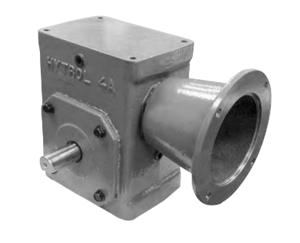
Daikin Hydraulic Unit EHU2507-40
Need answers fast?
Explore the manual using AI.
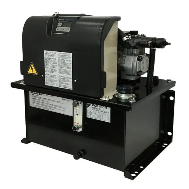
The Daikin Hydraulic Unit EHU2507-40 is a robust hydraulic system designed for industrial applications. Known for its reliability and efficiency, this unit supports various hydraulic functions, ensuring optimal performance in demanding environments. Regular maintenance and quality spare parts are essential for its longevity and operational excellence.
Turn manuals into instant answers
with your AI-powered assistantTurn manuals into instant answers
with your AI-powered assistant
Manual for Daikin Hydraulic Unit EHU2507-40
Complete asset maintenance, one click away
Get instant access to all the maintenance information you need. Empower technicians to perform preventive maintenance with asset packages, ready to use right out of the box.

Documents & Manuals
Find all the essential guides in one place.
 Tensioning Guide
- Belt-diagram
- C-120 pulleys
+ 13 more

Work Order Templates
Pre-built workflows to keep your asset running smoothly.
- Daily Electrical System Inspection
- Replace Roller and Pulley
- Install Engine B-120
+ 29 more

Procedures
Integrate maintenance plans directly into your work orders.
- Motion Industries
- Applied Industrial Technologies
- Electrical Brothers
+ 5 more

Parts
Access the parts list for your equipment in MaintainX.
- Drive Motor
- B2 Rollers
- Tensioning System
+ 40 more
Daikin Hydraulic Unit EHU2507-40
Create an account to install this asset package.
Maintenance Plans for Daikin Hydraulic Unit Model EHU2507-40
Integrate maintenance plans directly into your work orders in MaintainX.
1 Yearly Oil Filler Port Cum Air Breather Maintenance
- Removal method
• Turn the cap in the counterclockwise direction by hand and remove it.
- Cleaning
• Air blow the filter section to blow off deposits and adhering material. Also remove dirt from inside the strainer’s cylinder.
- Mounting
• Fit the cap by turning in the clockwise direction by hand to the position where it stops.
WARNING! When using air blow, wear protective glasses to avoid getting deposits and dirt in your eyes.;

1 Yearly Suction Strainer Maintenance
- Removal method
1. Set a drain oil receiver below the oil drainage port, open the oil drain plug (M12 × 20L), and drain out all of the hydraulic oil in the tank.
2. Remove the four hexagonal bolts (M8 × 20L) securing the top plate and tank, and hoist the motor by its suspension plates to separate it from the tank.
3. This will reveal the suction strainer: loosen it with e.g. an adjustable wrench and remove it.
- Cleaning
• Air blow the filter section to blow off deposits and adhering material. Also remove dirt from inside the strainer’s cylinder.
- Reassembly
• After completing the cleaning, reassemble by following the removal procedure in reverse. The tightening torque for the hexagonal bolts that secure the top plate and tank is 5.9 N⋅m. After completing reassembly, check that the unit runs normally by following the test run instructions.
WARNING! When using air blow, wear protective glasses to avoid getting deposits and dirt in your eyes.;
Fixed Throttle (φ0.8) Mounting
When using the unit with a set pressure of 6 MPa or higher, if the pressure becomes unstable due to the effects of contaminants, etc., mount the fixed throttle (φ0.8) provided as an accessory. Check that there is no residual pressure before mounting it.
1. Remove the hexagon socket head T plug (Rc 1/4).
2. Mount the fixed throttle (NPTF1/16 × φ0.8).
3. Wrap sealing tape around the hexagon socket head T plug (Rc 1/4) and fit it as it was.;
High-pressure Safety Valve Adjustment
If any of the three conditions below is applicable, readjust the safety valve.
1) Although the setting is such that even when used at the maximum pressure setting, the safety valve will not actuate under normal pressure control (there is an exception during transition to the main machine’s hydraulic circuit blockage due to a stop of a hydraulic actuator, for example), the set pressure of the safety valve drops and it actuates even in the normal status due to repeated operation over a protracted period or contaminants in the hydraulic oil.
• When the oil temperature rise has become faster in comparison with how it was previously.
• When, in the pressure holding state with the motor speed displayed, turning the safety valve adjusting screw in the tightening direction lowers the motor speed.
2) When, for reasons such as the restricted withstand pressure of the hoses used, it is desired to as far as possible suppress surge pressures that greatly exceed the set value.
3) When the pressure setting has been changed after shipment from Daikin. For the purpose of suppressing surge pressure in order to protect the main machine’s actuator and peripheral devices such as pressure gauges, it is advisable to set the safety valve setting to “unit set pressure + 0.5 MPa”.
1. Referring to the enlarged view of the safety valve on the next page, loosen the lock nut. (Lock nut: M10, width across flats of 14 mm)
2. In accordance with the guidance diagram for the length of the pressure adjusting screw, bring the screw to about the length corresponding to the desired control pressure. (The tip of the adjusting screw has four faces, with width across flats of 7 mm.)
3. Turn on the power to the hydraulic unit, establish the setting mode by panel key operation, and adjust the pressure setting to the desired pressure.
6 Monthly Hydraulic Unit Maintenance
CAUTION!
• Wear protective glasses and gloves for this work, and do it with the power OFF.
• When using air blow, take care to avoid getting foreign matter in your eyes.
• Note that oil will flow out from the piping during disassembly. Also, check that there is no residual pressure in the piping before starting the work.
• When the hydraulic oil in cylinders and piping is returned to the tank, the tank may overflow. Rather than returning the hydraulic oil in cylinders to the tank, collect it in a separate oil receiver.
• Check that there is no abnormal noise, abnormal vibration, or abnormal heat generation from this product.
1. Oil hue check. Degradation of the hydraulic oil can be recognized based on its color. If the hydraulic oil color changes toward brown and reaches ASTM level L4: bright yellow, replace it.
2. Check that there are no cracks or breaks in the sheathing of the wiring.
3. Measure the insulation resistance, and check that it has not dropped.
Unlock efficiency
with MaintainX CoPilot
MaintainX CoPilot is your expert colleague, on call 24/7, helping your team find the answers they need to keep equipment running.
Reduce Unplanned Downtime
Ensure your team follows consistent procedures to minimize equipment failures and costly delays.
Maximize Asset Availability
Keep your assets running longer and more reliably, with standardized maintenance workflows from OEM manuals.
Lower Maintenance Costs
Turn any technician into an expert to streamline operations, maintain more assets, and reduce overall costs.
Thousands of companies manage their assets with MaintainX

'%3e%3cpath%20fill='url(%23b)'%20d='M66.008%2080.068c-5.084-.786-9.763-3.834-12.442-8.68a16.942%2016.942%200%200%201-1.87-5.18c1.096.19%202.203.476%203.298.87%206.525%202.333%2010.836%207.68%2011.014%2012.99ZM51.47%2061.576c.488-5.524%203.62-10.716%208.847-13.597a17.132%2017.132%200%200%201%2011.335-1.882c-.798%208.145-7.43%2014.848-16.038%2015.599-1.417.119-2.799.07-4.144-.12Zm28.564-11.478a17.513%2017.513%200%200%201%203.727%204.62c4.608%208.335%201.584%2018.813-6.75%2023.409a16.988%2016.988%200%200%201-4.359%201.679%2019.624%2019.624%200%200%201-3.977-12.776c.346-7.561%204.942-13.931%2011.36-16.932Z'/%3e%3cpath%20fill='%23110F0D'%20fill-rule='evenodd'%20d='M142.831%2048.324h4.977V77.03h-4.977V48.324Zm27.278%2013.002c.322%201.048.453%202.263.453%203.62v12.073h-4.787V66.208c0-.75-.047-1.572-.154-2.143-.453-2.382-1.822-3.572-4.215-3.572-2.31%200-3.882%201.274-4.43%203.476-.143.596-.226%201.405-.226%202.25v10.8h-4.787V56.623h4.477v2.989c1.536-2.5%203.906-3.43%206.371-3.43%203.488%200%206.263%201.68%207.298%205.144Zm24.636%207.323c0%203.882-2.358%206.525-5.763%207.727-1.298.453-2.632.643-4.62.643h-10.169V48.324h9.085c1.691%200%203.156.143%204.049.38%203.465.93%205.727%203.68%205.727%207.335%200%202.441-.81%204.156-2.762%205.644%202.905%201.417%204.453%203.727%204.453%206.966Zm-15.634-8.656h4.584c1.024%200%201.917-.143%202.536-.417%201.215-.548%201.905-1.608%201.905-3.167%200-1.548-.643-2.572-1.845-3.132-.691-.31-1.762-.452-2.763-.452h-4.417v7.168Zm10.716%208.465c0-1.536-.893-3.37-3.227-3.893-.428-.095-1.036-.143-1.571-.143h-5.918v8.085h5.501c.56%200%201.429-.048%201.953-.167%201.94-.453%203.262-1.846%203.262-3.882Zm47.747-11.847-8.097%2020.408h-4.429l-8.109-20.408h5.191l5.192%2014.574%205.108-14.574h5.144Zm-20.218%2010.002c0%20.69-.036%201.262-.155%201.94h-15.943c.631%202.87%202.714%204.728%205.882%204.728%202.131%200%203.607-.882%204.703-2.525h4.87c-1.762%204.144-5.204%206.692-9.657%206.692-6.084%200-10.537-4.858-10.537-10.49%200-6.108%204.524-10.776%2010.335-10.776%206.239%200%2010.442%204.954%2010.502%2010.43Zm-4.763-1.405c-.333-2.846-2.643-4.858-5.691-4.858-2.894%200-5.287%201.929-5.621%204.858h11.312Zm-72.667%203.44c0%204.787-3.287%208.371-9.419%208.371H119.363V64.66c-1.917.274-3.87.69-5.811%201.238l4.537%2011.121h-5.418l-3.596-9.585c-5.144%202.084-10.085%205.216-14.217%209.585h-4.786L101.8%2048.312h4.56l5.68%2013.883a44.112%2044.112%200%200%201%207.323-1.774V48.312h9.084c1.703%200%203.156.143%204.061.393%203.453.929%205.727%203.667%205.727%207.323%200%201.917-.738%204.179-2.81%205.691%203.06%201.56%204.501%204.025%204.501%206.93Zm-15.634-8.667a62.664%2062.664%200%200%201%202.06-.036c1.703.012%203.239.131%204.608.37%201.441-.549%202.357-1.727%202.357-3.537%200-1.941-.881-3.144-2.488-3.667-.548-.18-1.358-.286-2.322-.286h-4.215v7.156Zm-16.55%203.905-3.715-9.894-6.394%2016.502c2.833-2.595%206.263-4.858%2010.109-6.608Zm27.254%204.74c0-2.775-3.131-4.347-8.513-4.418-.715%200-1.441.011-2.191.047v8.252h5.918c2.548%200%204.786-1.37%204.786-3.882Z'%20clip-rule='evenodd'/%3e%3c/g%3e%3cdefs%3e%3clinearGradient%20id='b'%20x1='51.47'%20x2='85.916'%20y1='62.946'%20y2='62.946'%20gradientUnits='userSpaceOnUse'%3e%3cstop%20stop-color='%23CD9F28'/%3e%3cstop%20offset='1'%20stop-color='%23ECD80B'/%3e%3c/linearGradient%3e%3cclipPath%20id='a'%3e%3cpath%20fill='%23fff'%20d='M51.47%2045.728h186.104V80.14H51.47z'/%3e%3c/clipPath%3e%3c/defs%3e%3c/svg%3e)


More from Daikin


Explore Other Assets


© 2026 MaintainX. All rights reserved.