


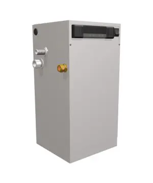
Boss Hydraulic Air Compressor BA440
Need answers fast?
Explore the manual using AI.
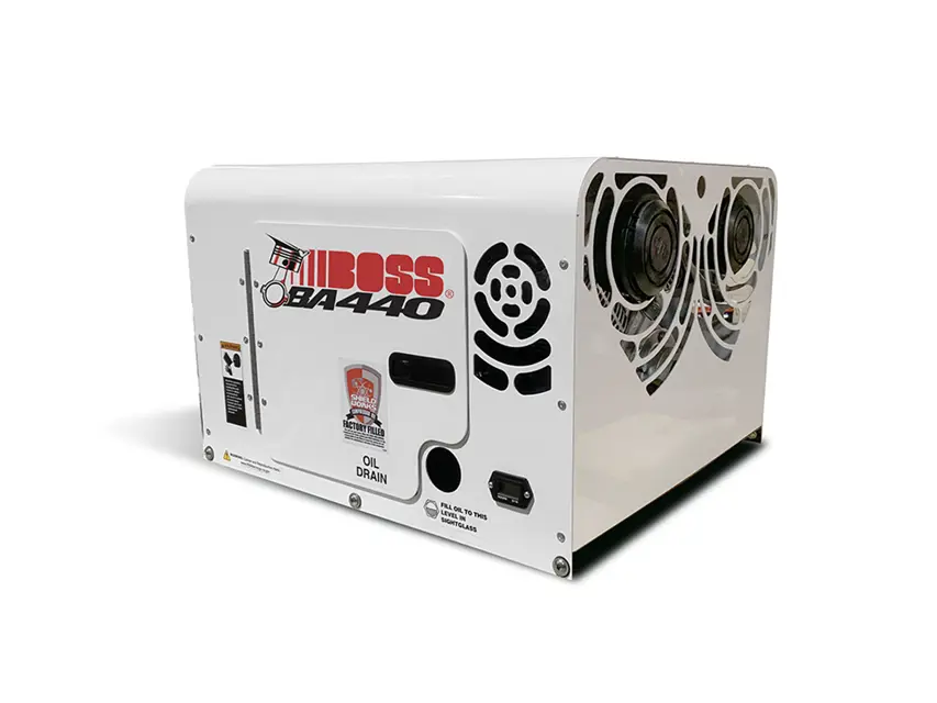
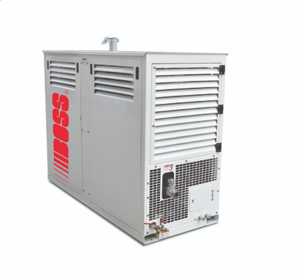
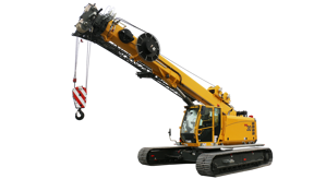
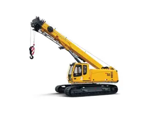
The Boss Hydraulic Air Compressor BA440 is a robust industrial compressor designed for high-performance applications. Known for its reliability and efficiency, this model is ideal for various pneumatic tasks in demanding environments, ensuring optimal air pressure and flow for your operations.
Turn manuals into instant answers
with your AI-powered assistantTurn manuals into instant answers
with your AI-powered assistant
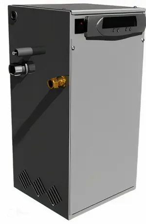
Manual for Boss Hydraulic Air Compressor BA440
Complete asset maintenance, one click away
Get instant access to all the maintenance information you need. Empower technicians to perform preventive maintenance with asset packages, ready to use right out of the box.

Documents & Manuals
Find all the essential guides in one place.
 Tensioning Guide
- Belt-diagram
- C-120 pulleys
+ 13 more

Work Order Templates
Pre-built workflows to keep your asset running smoothly.
- Daily Electrical System Inspection
- Replace Roller and Pulley
- Install Engine B-120
+ 29 more

Procedures
Integrate maintenance plans directly into your work orders.
- Motion Industries
- Applied Industrial Technologies
- Electrical Brothers
+ 5 more

Parts
Access the parts list for your equipment in MaintainX.
- Drive Motor
- B2 Rollers
- Tensioning System
+ 40 more
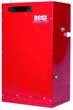
Boss Hydraulic Air Compressor BA440
Create an account to install this asset package.
Maintenance Plans for Boss Hydraulic Air Compressor Model BA440
Integrate maintenance plans directly into your work orders in MaintainX.
Maintenance 6M
1. Inspect the drive coupling for wear.
2. Change the air cleaner.;

Maintenance
Compressor Oil Fill, Level, and Drain
Before adding or changing compressor oil, make sure that the compressor is completely relieved of pressure. Oil is added at the fill cap on a pipe on the rear of the crankcase. A drain line is located on the rear panel of the machine. Proper oil level is to the “FULL” line on the dipstick, when the unit is shut down and has had time to settle. The machine must be level when checking the oil. DO NOT OVERFILL. The oil capacity is given in “Compressor Specifications”.
Changing the Air Intake Filter
The air intake filter is a heavy-duty dry type high efficiency filter designed to protect the compressor from dust and foreign objects.
Frequency of maintenance of the filter depends on dust conditions at the operating site. The filter element must be serviced when clogged. A clogged air filter element will reduce compressor performance and cause premature wear of components.
Changing the Hydraulic Oil Cooler
The interior of the oil cooler should be cleaned when the pressure drop across it at full flow exceeds 25 PSI. First, remove the cooler. Then, circulate a suitable solvent to dissolve and remove varnish and sludge. Then flush the cooler generously with hydraulic oil. Reinstall the cooler. Once the cooler is reinstalled, fill the hydraulic system with the proper fluid to their appropriate levels.
Piston Ring Replacement
Shut down the machine and allow to cool for approximately 10 minutes. Next, verify entire system pressure is relieved before proceeding. Then, disconnect air inlet system tubes. Now disconnect 3/4” discharge jumper hose and 3/4” discharge hose. Unscrew the head nuts and remove the heads.
Replacement
Oil Pump Replacement
First, shut down the machine and allow it to cool for at least 10 minutes. Verify that the entire system is pressure relived before proceeding. Next, remove the bolts and lift off the pump cover. Use a single edged razor blade or putty knife to remove the old gasket material, but make sure not to damage the machined surfaces.
Lift the pump out of the cavity and position a new gasket on the rear bearing housing. Next, insert the pump into the cavity and position it slightly to one side using a common screwdriver. Wedge the pump into he piston so that it partially compresses the spring. Note that the driver pin and slot in pump must be in line.
Next place the pump cover into position and start two bolts. Strike the pump cover with a rubber mallet to jar the pump loose. When the tension spring can be felt against the pump cover, the pump is lose. Now you can insert the two remaining bolts and torque to 180 in-lbs. The bolts should be torqued in a diagonal pattern. Finally, install the air compressor in the vehicle and connect air lines and wiring.
Crankshaft and Bearing Replacement
If it is necessary to replace the crankshaft, related components must also be replaced. Replace both bearings, both races, the key, pump collar, and pump drive pin.
First, shut down the machine and allow it to cool for at least 10 minutes. Verify that the entire system is pressure relived before proceeding. Remove both heads, cylinders, and pistons (See Piston Ring Replacement on pg. 16).
Next, remove the bolts on the connecting rods and lift them out. Reassemble the connecting rods to be certain that the matched parts remain together on the same crankshaft journals.
Now remove the pump cover, oil pump, sleeve, spring, and rear bearing housing. Next remove the drive hub and the front bearing housing. Next pull the crankshaft from the crankcase and remove all gasket material with a razor blade or putty knife.
Maintenance 1D
1. Check crankcase oil level.
2. Drain Condensation from air receiver.;
Check 1W
1. Inspect the air intake.
2. Check the cylinder head stud torque (See NOTE 2)
3. Check the operation of the receiver safety values.;
Parts for Boss Hydraulic Air Compressor BA440
Access the parts list for your equipment in MaintainX.
Kit, Repair Reed Valve
80279
Element, Air Filter
300854
Lubricant, Shieldworks 2Q
310610-2Q
Spider, Curved Jaw
301267
Kit, Repair Hyd Motor Seal
302936
Kit, Repair Reed Valve
80279
Element, Air Filter
300854
Lubricant, Shieldworks 2Q
310610-2Q
Spider, Curved Jaw
301267
Kit, Repair Hyd Motor Seal
302936
Kit, Repair Reed Valve
80279
Element, Air Filter
300854
Lubricant, Shieldworks 2Q
310610-2Q
Spider, Curved Jaw
301267
Kit, Repair Hyd Motor Seal
302936
Unlock efficiency
with MaintainX CoPilot
MaintainX CoPilot is your expert colleague, on call 24/7, helping your team find the answers they need to keep equipment running.
Reduce Unplanned Downtime
Ensure your team follows consistent procedures to minimize equipment failures and costly delays.
Maximize Asset Availability
Keep your assets running longer and more reliably, with standardized maintenance workflows from OEM manuals.
Lower Maintenance Costs
Turn any technician into an expert to streamline operations, maintain more assets, and reduce overall costs.
Thousands of companies manage their assets with MaintainX

'%3e%3cpath%20fill='url(%23b)'%20d='M66.008%2080.068c-5.084-.786-9.763-3.834-12.442-8.68a16.942%2016.942%200%200%201-1.87-5.18c1.096.19%202.203.476%203.298.87%206.525%202.333%2010.836%207.68%2011.014%2012.99ZM51.47%2061.576c.488-5.524%203.62-10.716%208.847-13.597a17.132%2017.132%200%200%201%2011.335-1.882c-.798%208.145-7.43%2014.848-16.038%2015.599-1.417.119-2.799.07-4.144-.12Zm28.564-11.478a17.513%2017.513%200%200%201%203.727%204.62c4.608%208.335%201.584%2018.813-6.75%2023.409a16.988%2016.988%200%200%201-4.359%201.679%2019.624%2019.624%200%200%201-3.977-12.776c.346-7.561%204.942-13.931%2011.36-16.932Z'/%3e%3cpath%20fill='%23110F0D'%20fill-rule='evenodd'%20d='M142.831%2048.324h4.977V77.03h-4.977V48.324Zm27.278%2013.002c.322%201.048.453%202.263.453%203.62v12.073h-4.787V66.208c0-.75-.047-1.572-.154-2.143-.453-2.382-1.822-3.572-4.215-3.572-2.31%200-3.882%201.274-4.43%203.476-.143.596-.226%201.405-.226%202.25v10.8h-4.787V56.623h4.477v2.989c1.536-2.5%203.906-3.43%206.371-3.43%203.488%200%206.263%201.68%207.298%205.144Zm24.636%207.323c0%203.882-2.358%206.525-5.763%207.727-1.298.453-2.632.643-4.62.643h-10.169V48.324h9.085c1.691%200%203.156.143%204.049.38%203.465.93%205.727%203.68%205.727%207.335%200%202.441-.81%204.156-2.762%205.644%202.905%201.417%204.453%203.727%204.453%206.966Zm-15.634-8.656h4.584c1.024%200%201.917-.143%202.536-.417%201.215-.548%201.905-1.608%201.905-3.167%200-1.548-.643-2.572-1.845-3.132-.691-.31-1.762-.452-2.763-.452h-4.417v7.168Zm10.716%208.465c0-1.536-.893-3.37-3.227-3.893-.428-.095-1.036-.143-1.571-.143h-5.918v8.085h5.501c.56%200%201.429-.048%201.953-.167%201.94-.453%203.262-1.846%203.262-3.882Zm47.747-11.847-8.097%2020.408h-4.429l-8.109-20.408h5.191l5.192%2014.574%205.108-14.574h5.144Zm-20.218%2010.002c0%20.69-.036%201.262-.155%201.94h-15.943c.631%202.87%202.714%204.728%205.882%204.728%202.131%200%203.607-.882%204.703-2.525h4.87c-1.762%204.144-5.204%206.692-9.657%206.692-6.084%200-10.537-4.858-10.537-10.49%200-6.108%204.524-10.776%2010.335-10.776%206.239%200%2010.442%204.954%2010.502%2010.43Zm-4.763-1.405c-.333-2.846-2.643-4.858-5.691-4.858-2.894%200-5.287%201.929-5.621%204.858h11.312Zm-72.667%203.44c0%204.787-3.287%208.371-9.419%208.371H119.363V64.66c-1.917.274-3.87.69-5.811%201.238l4.537%2011.121h-5.418l-3.596-9.585c-5.144%202.084-10.085%205.216-14.217%209.585h-4.786L101.8%2048.312h4.56l5.68%2013.883a44.112%2044.112%200%200%201%207.323-1.774V48.312h9.084c1.703%200%203.156.143%204.061.393%203.453.929%205.727%203.667%205.727%207.323%200%201.917-.738%204.179-2.81%205.691%203.06%201.56%204.501%204.025%204.501%206.93Zm-15.634-8.667a62.664%2062.664%200%200%201%202.06-.036c1.703.012%203.239.131%204.608.37%201.441-.549%202.357-1.727%202.357-3.537%200-1.941-.881-3.144-2.488-3.667-.548-.18-1.358-.286-2.322-.286h-4.215v7.156Zm-16.55%203.905-3.715-9.894-6.394%2016.502c2.833-2.595%206.263-4.858%2010.109-6.608Zm27.254%204.74c0-2.775-3.131-4.347-8.513-4.418-.715%200-1.441.011-2.191.047v8.252h5.918c2.548%200%204.786-1.37%204.786-3.882Z'%20clip-rule='evenodd'/%3e%3c/g%3e%3cdefs%3e%3clinearGradient%20id='b'%20x1='51.47'%20x2='85.916'%20y1='62.946'%20y2='62.946'%20gradientUnits='userSpaceOnUse'%3e%3cstop%20stop-color='%23CD9F28'/%3e%3cstop%20offset='1'%20stop-color='%23ECD80B'/%3e%3c/linearGradient%3e%3cclipPath%20id='a'%3e%3cpath%20fill='%23fff'%20d='M51.47%2045.728h186.104V80.14H51.47z'/%3e%3c/clipPath%3e%3c/defs%3e%3c/svg%3e)


More from Boss


Explore Other Assets


© 2026 MaintainX. All rights reserved.