


Baker Hughes Baker Hughes Cylinder Actuator 51/52/53 Series 51/52/53 Series
Need answers fast?
Explore the manual using AI.
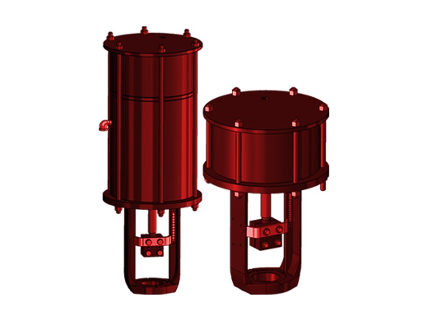
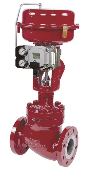
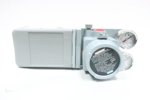
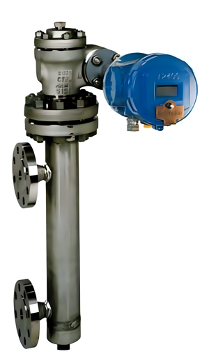
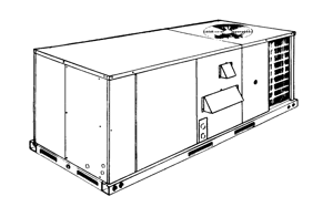
The Baker Hughes Cylinder Actuator 51/52/53 Series is a robust and reliable actuator designed for industrial applications. Known for its precision and durability, this actuator series ensures optimal performance and efficiency in various operational environments. Regular maintenance and quality spare parts are essential for maximizing its lifespan and functionality.
Turn manuals into instant answers
with your AI-powered assistantTurn manuals into instant answers
with your AI-powered assistant
Manual for Baker Hughes Baker Hughes Cylinder Actuator 51/52/53 Series 51/52/53 Series
Complete asset maintenance, one click away
Get instant access to all the maintenance information you need. Empower technicians to perform preventive maintenance with asset packages, ready to use right out of the box.

Documents & Manuals
Find all the essential guides in one place.
 Tensioning Guide
- Belt-diagram
- C-120 pulleys
+ 13 more

Work Order Templates
Pre-built workflows to keep your asset running smoothly.
- Daily Electrical System Inspection
- Replace Roller and Pulley
- Install Engine B-120
+ 29 more

Procedures
Integrate maintenance plans directly into your work orders.
- Motion Industries
- Applied Industrial Technologies
- Electrical Brothers
+ 5 more

Parts
Access the parts list for your equipment in MaintainX.
- Drive Motor
- B2 Rollers
- Tensioning System
+ 40 more
Baker Hughes Baker Hughes Cylinder Actuator 51/52/53 Series 51/52/53 Series
Create an account to install this asset package.
Maintenance Plans for Baker Hughes Baker Hughes Cylinder Actuator 51/52/53 Series Model 51/52/53 Series
Integrate maintenance plans directly into your work orders in MaintainX.
Model 51 O-ring, Guide Ring Replacement - Double Acting With/Without Handwheel
- Place the actuators in an upright position for all disassembly or assembly operations.
- Ensure that guide bushing inner surface (32) is not scratched by Piston subassembly screw (31).
- The handwheel must be in the AUTO position.
- Shut off air supply to the actuator, and isolate the process pressure from the valve to prevent plug movement.
- Disconnect air piping from the Top Plate (17), Separator Plate (69), and check for air pressure in the cylinder.
- Remove the Hexagon Nuts (20), Spring Lock Washers (29), and Center Bolts (19).
- For models with Volume Chamber: Remove Top Plate (17), Volume Chamber Tube (70), Separator Plate (69), Cylinder Tube (14), O-rings (21), Guide Ring (16).
- Without Volume Chamber: Remove Top Plate (17), Cylinder Tube (14), O-rings (21), Guide Ring (16).
- Loosen Set Screw (55) in Adapter (54) and unscrew Adapter (54) from Spacer Tube (5).

Model 52 O-ring, Guide Ring Replacement - Air-to-Extend with Handwheel
- The handwheel must be in the AUTO position.
- Shut off air supply to the actuator, and isolate the process pressure from the valve.
- Disconnect air piping from the top plate.
- Remove the Hexagon Nuts (20), Spring Lock Washers (29), and Center Bolts (19).
- Remove the Top Plate (17) and Cylinder Tube (14), carefully avoiding any horizontal misalignment.
- Replace the O-ring (21) on the Top Plate (17) and the O-ring (21) and Guide Ring (16) on the Piston Plate S/A (15) with new parts. Coat the O-rings and Guide Ring with silicone grease (or equivalent). Coat the sliding surface of the Compression Bolt with industrial grease (not silicone grease).
- Replace Cylinder Tube (14), and Top Plate (17) with only axial movement. Coat the inner surface of the Cylinder Tube with silicone grease.
- Ensure the positions of the air connections are correct. Insert the Center Bolts into the holes of the Top Plate and Yoke. Mount the Spring Washers and Nuts and tighten them lightly by hand. Mount the Spring Washers and Nuts to the bottom side of the Yoke by hand. Ensure that the position of Center Bolts (Approximately +25 mm longer than others) for the accessory mounting plate, if equipped, complies with Figure 13.
- Align the holes of the Top Plate with the Yoke so that the Center Bolts are set vertically.
Model 53 O-ring and Guide Ring Replacement - Air to Retract with Handwheel
- The handwheel must be in the AUTO position.
- Shut off the air supply to the actuator, and isolate the process pressure from the valve.
- Remove the Indicator Arm (23), Split Clamp (22), Hexagon Bolts (24) and Spring Lock Washers (25).
- Remove the Hexagon Nuts (20), Spring Lock Washers (29), and Center Bolts (19).
- Remove Top Plate (17), Spring Tube (7), and spring unit.
- Remove Separator Plate (13), Cylinder Tube (14), O-ring (21), Guide Ring (16).
- Remove Piston Subassembly (31).
- Unscrew Locking Nut (42) and Adjustment Nut (43).
- Replace O-ring (33) on Piston Rod with new part. Coat the O-ring with silicone grease (or equivalent).
Model 52 O-ring, Guide Ring and Rod Scraper Replacement - Air-to-Extend Without Handwheel
- Shut off the air supply to the actuator, and isolate the process pressure from the valve.
- Disconnect supply piping from the Top Plate.
- Remove the Indicator Arm (23), Split Clamp (22), Hexagon Bolts (24) and Spring Lock Washers (25).
- Remove the Hexagon Nuts (20), Spring Lock Washers (29), and Center Bolts (19).
- Remove the Top Plate (17) and Cylinder Tube (14), carefully avoiding any horizontal misalignment.
- Replace the O-ring (21) on the Top Plate (17) and the O-ring (21) and Guide Ring (16) on the Piston Plate (15) with new parts. Coat the O-rings and Guide Ring with silicone grease (or equivalent).
- Rotate the Piston Plate subassembly (15) until the chamfer in the Compression Nut (12) aligns with the stop collar opening in the Piston Plate subassembly.
- Remove Piston Plate subassembly (15) in the direction of an arrow.
- Remove Separator Plate (13), Spring Tube (7) and spring subassembly.
Model 53 O-ring, Guide Ring and Rod Scraper Replacement - Air-to-Retract Without Handwheel
- Shut off the air supply to the actuator, and isolate the process pressure from the valve.
- Remove the Indicator Arm (23), Split Clamp (22), Hexagon Bolts (24) and Spring Lock Washers (25).
- Remove the Hexagon Nuts (20), Spring Lock Washers (29), and Center Bolts (19). Disassemble the Hex Nuts (20) in small increments using an alternating diagonal pattern to slowly relieve the spring tension.
- Remove Top Plate (17), Spring Tube (7), and spring unit.
- Remove Separator Plate (13), Cylinder Tube (14), O-ring (21), Guide Ring (16).
- Remove Piston Subassembly (31).
- Replace O-ring (33) and Rod Scraper (34) with new parts. Coat the O-ring and Rod Scraper with silicone grease (or equivalent).
- Replace Piston Subassembly (31).
- Replace O-ring (21) and Guide Ring (16) with new parts. Coat the O-ring and Guide Ring with silicone grease (or equivalent).
Parts for Baker Hughes Baker Hughes Cylinder Actuator 51/52/53 Series 51/52/53 Series
Access the parts list for your equipment in MaintainX.
Handwheel
-
Directional Plate
-
Grip
-
Retaining Ring
-
Split Clamp
-
Handwheel
-
Directional Plate
-
Grip
-
Retaining Ring
-
Split Clamp
-
Handwheel
-
Directional Plate
-
Grip
-
Retaining Ring
-
Split Clamp
-
Unlock efficiency
with MaintainX CoPilot
MaintainX CoPilot is your expert colleague, on call 24/7, helping your team find the answers they need to keep equipment running.
Reduce Unplanned Downtime
Ensure your team follows consistent procedures to minimize equipment failures and costly delays.
Maximize Asset Availability
Keep your assets running longer and more reliably, with standardized maintenance workflows from OEM manuals.
Lower Maintenance Costs
Turn any technician into an expert to streamline operations, maintain more assets, and reduce overall costs.
Thousands of companies manage their assets with MaintainX

'%3e%3cpath%20fill='url(%23b)'%20d='M66.008%2080.068c-5.084-.786-9.763-3.834-12.442-8.68a16.942%2016.942%200%200%201-1.87-5.18c1.096.19%202.203.476%203.298.87%206.525%202.333%2010.836%207.68%2011.014%2012.99ZM51.47%2061.576c.488-5.524%203.62-10.716%208.847-13.597a17.132%2017.132%200%200%201%2011.335-1.882c-.798%208.145-7.43%2014.848-16.038%2015.599-1.417.119-2.799.07-4.144-.12Zm28.564-11.478a17.513%2017.513%200%200%201%203.727%204.62c4.608%208.335%201.584%2018.813-6.75%2023.409a16.988%2016.988%200%200%201-4.359%201.679%2019.624%2019.624%200%200%201-3.977-12.776c.346-7.561%204.942-13.931%2011.36-16.932Z'/%3e%3cpath%20fill='%23110F0D'%20fill-rule='evenodd'%20d='M142.831%2048.324h4.977V77.03h-4.977V48.324Zm27.278%2013.002c.322%201.048.453%202.263.453%203.62v12.073h-4.787V66.208c0-.75-.047-1.572-.154-2.143-.453-2.382-1.822-3.572-4.215-3.572-2.31%200-3.882%201.274-4.43%203.476-.143.596-.226%201.405-.226%202.25v10.8h-4.787V56.623h4.477v2.989c1.536-2.5%203.906-3.43%206.371-3.43%203.488%200%206.263%201.68%207.298%205.144Zm24.636%207.323c0%203.882-2.358%206.525-5.763%207.727-1.298.453-2.632.643-4.62.643h-10.169V48.324h9.085c1.691%200%203.156.143%204.049.38%203.465.93%205.727%203.68%205.727%207.335%200%202.441-.81%204.156-2.762%205.644%202.905%201.417%204.453%203.727%204.453%206.966Zm-15.634-8.656h4.584c1.024%200%201.917-.143%202.536-.417%201.215-.548%201.905-1.608%201.905-3.167%200-1.548-.643-2.572-1.845-3.132-.691-.31-1.762-.452-2.763-.452h-4.417v7.168Zm10.716%208.465c0-1.536-.893-3.37-3.227-3.893-.428-.095-1.036-.143-1.571-.143h-5.918v8.085h5.501c.56%200%201.429-.048%201.953-.167%201.94-.453%203.262-1.846%203.262-3.882Zm47.747-11.847-8.097%2020.408h-4.429l-8.109-20.408h5.191l5.192%2014.574%205.108-14.574h5.144Zm-20.218%2010.002c0%20.69-.036%201.262-.155%201.94h-15.943c.631%202.87%202.714%204.728%205.882%204.728%202.131%200%203.607-.882%204.703-2.525h4.87c-1.762%204.144-5.204%206.692-9.657%206.692-6.084%200-10.537-4.858-10.537-10.49%200-6.108%204.524-10.776%2010.335-10.776%206.239%200%2010.442%204.954%2010.502%2010.43Zm-4.763-1.405c-.333-2.846-2.643-4.858-5.691-4.858-2.894%200-5.287%201.929-5.621%204.858h11.312Zm-72.667%203.44c0%204.787-3.287%208.371-9.419%208.371H119.363V64.66c-1.917.274-3.87.69-5.811%201.238l4.537%2011.121h-5.418l-3.596-9.585c-5.144%202.084-10.085%205.216-14.217%209.585h-4.786L101.8%2048.312h4.56l5.68%2013.883a44.112%2044.112%200%200%201%207.323-1.774V48.312h9.084c1.703%200%203.156.143%204.061.393%203.453.929%205.727%203.667%205.727%207.323%200%201.917-.738%204.179-2.81%205.691%203.06%201.56%204.501%204.025%204.501%206.93Zm-15.634-8.667a62.664%2062.664%200%200%201%202.06-.036c1.703.012%203.239.131%204.608.37%201.441-.549%202.357-1.727%202.357-3.537%200-1.941-.881-3.144-2.488-3.667-.548-.18-1.358-.286-2.322-.286h-4.215v7.156Zm-16.55%203.905-3.715-9.894-6.394%2016.502c2.833-2.595%206.263-4.858%2010.109-6.608Zm27.254%204.74c0-2.775-3.131-4.347-8.513-4.418-.715%200-1.441.011-2.191.047v8.252h5.918c2.548%200%204.786-1.37%204.786-3.882Z'%20clip-rule='evenodd'/%3e%3c/g%3e%3cdefs%3e%3clinearGradient%20id='b'%20x1='51.47'%20x2='85.916'%20y1='62.946'%20y2='62.946'%20gradientUnits='userSpaceOnUse'%3e%3cstop%20stop-color='%23CD9F28'/%3e%3cstop%20offset='1'%20stop-color='%23ECD80B'/%3e%3c/linearGradient%3e%3cclipPath%20id='a'%3e%3cpath%20fill='%23fff'%20d='M51.47%2045.728h186.104V80.14H51.47z'/%3e%3c/clipPath%3e%3c/defs%3e%3c/svg%3e)


More from Baker Hughes


Explore Other Assets


© 2025 MaintainX. All rights reserved.