


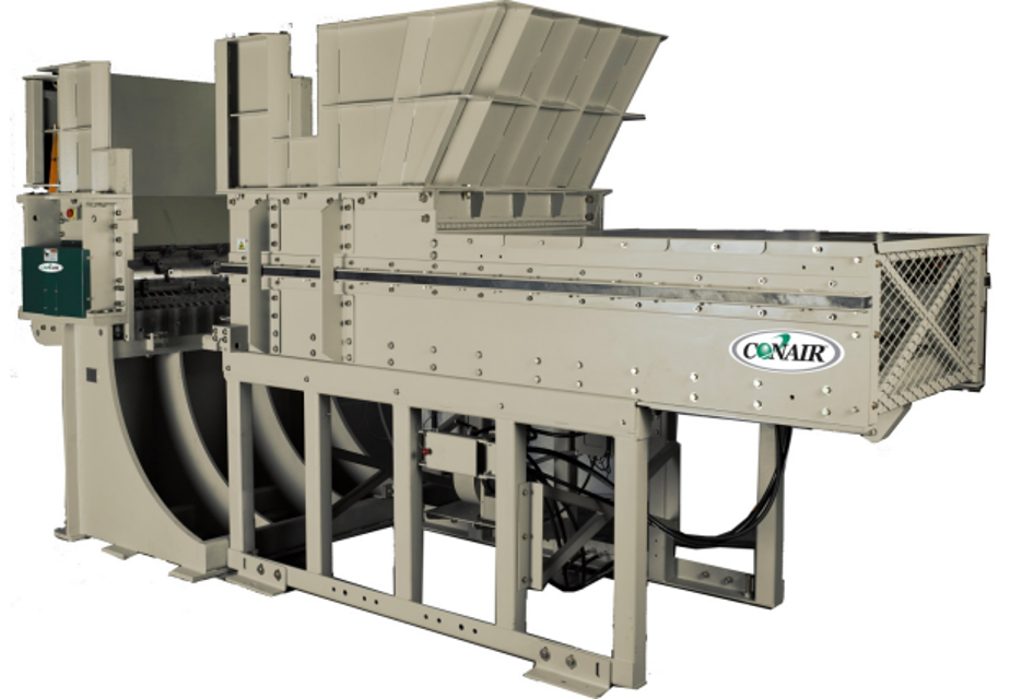
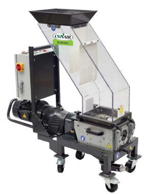
The Piovan Group Shredder SFX is a high-performance industrial shredder designed for efficient material processing. Known for its robust construction and advanced features, the SFX model ensures reliable operation and optimal shredding capabilities in various applications. Enhance your production line with this essential asset from Piovan Group.
Turn manuals into instant answers
with your AI-powered assistantTurn manuals into instant answers
with your AI-powered assistant
Complete asset maintenance, one click away
Get instant access to all the maintenance information you need. Empower technicians to perform preventive maintenance with asset packages, ready to use right out of the box.

Documents & Manuals
Find all the essential guides in one place.
 Tensioning Guide
- Belt-diagram
- C-120 pulleys
+ 13 more

Work Order Templates
Pre-built workflows to keep your asset running smoothly.
- Daily Electrical System Inspection
- Replace Roller and Pulley
- Install Engine B-120
+ 29 more

Procedures
Integrate maintenance plans directly into your work orders.
- Motion Industries
- Applied Industrial Technologies
- Electrical Brothers
+ 5 more

Parts
Access the parts list for your equipment in MaintainX.
- Drive Motor
- B2 Rollers
- Tensioning System
+ 40 more
Piovan Group Shredder SFX
Create an account to install this asset package.
Maintenance Plans for Piovan Group Shredder Model SFX
Integrate maintenance plans directly into your work orders in MaintainX.
1 Weekly Inspection
- Inspect the screen condition and mounting for tightness, damage, and deformation
- When replacement or removal is required the following procedure should be followed:
1. Follow all "Lock Out" procedures to insure machine cannot be operated while procedure is performed
2. Remove mounting bolts that secure screen to machine
3. Remove screen from discharge area
4. Inspect mounting holes to insure threaded hole is clean from debris and foreign materials and threads are not damaged
5. Install and locate screen to machine using suitable pry bar or lifting devise. Install mounting bolts and washers
6. Locate screen in such a position as to insure no interference with rotor assembly is present
7. Tighten mounting bolts to proper torque starting at center of screen working outward

1 Monthly Inspection
- Inspect Visually Torque Arm
- Inspect bushing for fatigue cracks in rubber cushion area. Inspect bushing pin bore for excessive movement between diameter and bore of bushing. The bushings are pressed into the torque arm assembly; therefore it is recommended to replace torque arm assembly and adjusting pin if bushing replacement is necessary
- Inspect Ram Wipers. Replacement will be necessary when 5/8" to 3/4" of wear is present (page 47)
- Inspect for wear on monthly basis. They are generally considered worn when approximately 1/8” from original specs and should be replaced (page 48)
- The hydraulics power system employs a high quality return oil filter (page 49). The filter has an indicator that changes color when it is time to be changed. Check filter every 30 days. The hydraulic fluid should last indefinitely unless it suffers severe overheating
- Inspect breather filter and replace when required. If machine is operated in extreme temperature conditions, adding an oil heater or oil cooler may be required
- The oil level in the tank should be checked on a regular basis. Refill hydraulic oil as necessary with this oil or equivalent. Do not overfill the hydraulic tank with oil. - The hydraulic cylinder requires lubrication to clevis pins. Grease fittings located on clevis eye require lubrication with grease once monthly. Visually inspect following items frequently:
1 Inspect all lines and fittings for leakage
2 Inspect rod end of cylinder for leakage at packing cap seals
4000 Hours Oil Replacement
- Fluid coupling oil should be replaced after every 4000 hours of service. Refill fluid coupling oil as necessary according to the manufacturer’s recommendations. Do not overfill the fluid coupling with oil. Refer to the fluid coupling manufacturer’s maintenance manual that was provided with this manual;
6 Monthly Check
- The oil level in the gearbox should be checked on a regular basis
- The oil level in the fluid coupling should be checked on a regular basis. Fluid coupling oil should be checked after every 6 months of operation (fluid should be cold while performing check)
- If the fusible plug blows at regular intervals in normal service, check the following listed possible causes for correction. High oil operating temperature can be caused by the following:
1 Insufficient oil level
2 Absorbed power is higher than the motor rated power
3 High ambient temperature
4 Too frequent starts
5 Long starting time
6 Inadequate air ventilation to allow cooling of the coupling. If coupling is operated in a restricted space, adequate ventilation apertures should be provided;
50 Hours Lubrication
- If rotor removal is required, you should consult Conair Service (800-458-1960) for resetting the bearings on the rotor
- Pillow Block Bearings should be lubricated on a regular basis. The recommended cycle to grease these bearings is every 50 hours of operation. Do not over grease. Shell Albida 220 Synthetic Lithium Complex grease or equivalent should be used (page 41). (Refer to manufacturer’s manual provided);
Parts for Piovan Group Shredder SFX
Access the parts list for your equipment in MaintainX.
Bolt
-
Counterknife
-
Washer
-
Rotor Door
-
Guide Block
-
Bolt
-
Counterknife
-
Washer
-
Rotor Door
-
Guide Block
-
Bolt
-
Counterknife
-
Washer
-
Rotor Door
-
Guide Block
-
Unlock efficiency
with MaintainX CoPilot
MaintainX CoPilot is your expert colleague, on call 24/7, helping your team find the answers they need to keep equipment running.
Reduce Unplanned Downtime
Ensure your team follows consistent procedures to minimize equipment failures and costly delays.
Maximize Asset Availability
Keep your assets running longer and more reliably, with standardized maintenance workflows from OEM manuals.
Lower Maintenance Costs
Turn any technician into an expert to streamline operations, maintain more assets, and reduce overall costs.
Thousands of companies manage their assets with MaintainX

'%3e%3cpath%20fill='url(%23b)'%20d='M66.008%2080.068c-5.084-.786-9.763-3.834-12.442-8.68a16.942%2016.942%200%200%201-1.87-5.18c1.096.19%202.203.476%203.298.87%206.525%202.333%2010.836%207.68%2011.014%2012.99ZM51.47%2061.576c.488-5.524%203.62-10.716%208.847-13.597a17.132%2017.132%200%200%201%2011.335-1.882c-.798%208.145-7.43%2014.848-16.038%2015.599-1.417.119-2.799.07-4.144-.12Zm28.564-11.478a17.513%2017.513%200%200%201%203.727%204.62c4.608%208.335%201.584%2018.813-6.75%2023.409a16.988%2016.988%200%200%201-4.359%201.679%2019.624%2019.624%200%200%201-3.977-12.776c.346-7.561%204.942-13.931%2011.36-16.932Z'/%3e%3cpath%20fill='%23110F0D'%20fill-rule='evenodd'%20d='M142.831%2048.324h4.977V77.03h-4.977V48.324Zm27.278%2013.002c.322%201.048.453%202.263.453%203.62v12.073h-4.787V66.208c0-.75-.047-1.572-.154-2.143-.453-2.382-1.822-3.572-4.215-3.572-2.31%200-3.882%201.274-4.43%203.476-.143.596-.226%201.405-.226%202.25v10.8h-4.787V56.623h4.477v2.989c1.536-2.5%203.906-3.43%206.371-3.43%203.488%200%206.263%201.68%207.298%205.144Zm24.636%207.323c0%203.882-2.358%206.525-5.763%207.727-1.298.453-2.632.643-4.62.643h-10.169V48.324h9.085c1.691%200%203.156.143%204.049.38%203.465.93%205.727%203.68%205.727%207.335%200%202.441-.81%204.156-2.762%205.644%202.905%201.417%204.453%203.727%204.453%206.966Zm-15.634-8.656h4.584c1.024%200%201.917-.143%202.536-.417%201.215-.548%201.905-1.608%201.905-3.167%200-1.548-.643-2.572-1.845-3.132-.691-.31-1.762-.452-2.763-.452h-4.417v7.168Zm10.716%208.465c0-1.536-.893-3.37-3.227-3.893-.428-.095-1.036-.143-1.571-.143h-5.918v8.085h5.501c.56%200%201.429-.048%201.953-.167%201.94-.453%203.262-1.846%203.262-3.882Zm47.747-11.847-8.097%2020.408h-4.429l-8.109-20.408h5.191l5.192%2014.574%205.108-14.574h5.144Zm-20.218%2010.002c0%20.69-.036%201.262-.155%201.94h-15.943c.631%202.87%202.714%204.728%205.882%204.728%202.131%200%203.607-.882%204.703-2.525h4.87c-1.762%204.144-5.204%206.692-9.657%206.692-6.084%200-10.537-4.858-10.537-10.49%200-6.108%204.524-10.776%2010.335-10.776%206.239%200%2010.442%204.954%2010.502%2010.43Zm-4.763-1.405c-.333-2.846-2.643-4.858-5.691-4.858-2.894%200-5.287%201.929-5.621%204.858h11.312Zm-72.667%203.44c0%204.787-3.287%208.371-9.419%208.371H119.363V64.66c-1.917.274-3.87.69-5.811%201.238l4.537%2011.121h-5.418l-3.596-9.585c-5.144%202.084-10.085%205.216-14.217%209.585h-4.786L101.8%2048.312h4.56l5.68%2013.883a44.112%2044.112%200%200%201%207.323-1.774V48.312h9.084c1.703%200%203.156.143%204.061.393%203.453.929%205.727%203.667%205.727%207.323%200%201.917-.738%204.179-2.81%205.691%203.06%201.56%204.501%204.025%204.501%206.93Zm-15.634-8.667a62.664%2062.664%200%200%201%202.06-.036c1.703.012%203.239.131%204.608.37%201.441-.549%202.357-1.727%202.357-3.537%200-1.941-.881-3.144-2.488-3.667-.548-.18-1.358-.286-2.322-.286h-4.215v7.156Zm-16.55%203.905-3.715-9.894-6.394%2016.502c2.833-2.595%206.263-4.858%2010.109-6.608Zm27.254%204.74c0-2.775-3.131-4.347-8.513-4.418-.715%200-1.441.011-2.191.047v8.252h5.918c2.548%200%204.786-1.37%204.786-3.882Z'%20clip-rule='evenodd'/%3e%3c/g%3e%3cdefs%3e%3clinearGradient%20id='b'%20x1='51.47'%20x2='85.916'%20y1='62.946'%20y2='62.946'%20gradientUnits='userSpaceOnUse'%3e%3cstop%20stop-color='%23CD9F28'/%3e%3cstop%20offset='1'%20stop-color='%23ECD80B'/%3e%3c/linearGradient%3e%3cclipPath%20id='a'%3e%3cpath%20fill='%23fff'%20d='M51.47%2045.728h186.104V80.14H51.47z'/%3e%3c/clipPath%3e%3c/defs%3e%3c/svg%3e)


More from Piovan Group


Explore Other Assets


© 2026 MaintainX. All rights reserved.