(Chipper) SHREDDER WL 6 WEIMA
This maintenance procedure can help restore your shredders operation and performance running at its best.
(Chipper) SHREDDER WL 6 WEIMA
This maintenance procedure can help restore your shredders operation and performance running at its best.
CAUTION! DANGER FROM SHARD EDGES ON THE BLADES/ COUNTER BLADES (cuts to arms and hands) -Wear protective gloves and long-sleeve protective clothing. Maintenance works are only allowed to be done by trained personnel. -Turn the machine off -Make sure that the machine cannot be turned on accidentally -Attach a safety sign "Do not switch on! Men working on equipment" on the switch cabinet. Compliance with the inspection intervals is one of the warranty conditions. MAINTENANCE INTERVAL MAINTENANCE IN OPERATING HOURS --------------------------------------------------------------- During operation the -Check hydraulic lines/piping/ machine /before each start fittings of the hydraulic unit of shift for leakage -Check hydraulic unit for leaks -Check the oil level in the hydraulic unit and refill if necessary (during a complete work cycle. The level must be between the min and max marks -Check the mechanical connections -Check the emergency stop feature -Check the safety switch function -Check the electric motor (fan) and clean if necessary. -Check rotor, in particular knives, blade holders and counter knives for damage and wear; adjust or replace if necessary. -Clean the interior of the machine and check for damage and wear. During the first 8 hr after -Check the operating temperature start up the hydraulic oil. -Check the gear oil -Check the electrical connections on the machine and on the hydraulic unit. -Check the V Belts, and tension if necessary. 100 Hrs after start up -Change oil filters Every 50 Hrs -Check the broaching knives on the rotor for wear. -Check the mechanical connections. -Check the V belts, and tension if necessary. -Lubricate the bearings (See Lubricating Instructions) Every 100 Hrs -Clean the space below the machine Every 250 Hrs -Check the gearbox for leaks Every 500 Hrs -Check all mechanical connections, in particular -Screen mount -Torque support -Mountings of all hydraulic cylinders -Gearbox mount
MAINTENANCE 2
Apply thread locks to all screws when screwing them in. STRENGTH STRENGTH STRENGTH CLASS 8.8 CLASS 10.9 CLASS 12.9 --------------------------------------------------------------------- SIZE TORQUE SPECS TORQUE SPECS TORQUE SPECS IN Nm IN Nm IN Nm --------------------------------------------------------------------- M8 23 34 40 M10 50 67 79 M12 85 125 135 M14 125 185 220 M16 210 290 340 M20 395 400 660 M24 680 730 1150 M30 (1420) (2033) (2380) M36 (2482) (3535) (4136) Bracket Values: Theoretical Values at 9- percent use of Rp0.2 and total= 0.12 TAPER LOCK TORQUE SPECIFICATIONS BUSHING IN Nm ------------------------------------------------ 2012 31 2517 48 3020 90 3030 90 3535 112 4040 170 4545 192 5050 271
MAINTENANCE 3
Service life as per DIN 20066 -When used for the first time, the hoses may not be older than four years (assembly of fittings). -The maximum service life of the hydraulic hoses is 6 years, including a possible storage time of maximum 2 years. For hydraulic hoses used refer to Appendix "List of Hydraulic Hoses" or on the hydraulic hoses of the pressed fittings CRITERIA FOR REPLACEMENT OF HYDRAULIC HOSES Replace the hydraulic hoses when the following deficiencies occur: - Damage of the external layer until the inlay, e.g. due to rubbed surfaces, cuts or cracks. -Embrittlement of the external surface due to the forma- tion of cracks in the hose material. -Deformation that do not refer to the natural shape of the hose or the hose line, when pressureless as well as pressurized or bent. -Formation of bubbles -Damage or deformation of the hose fittings -Hose migrates out of the fitting. -Corrosion of fitting reducing the function and the strength. -Storage and service life fo the hose material exceeded.
MAINTENANCE 4
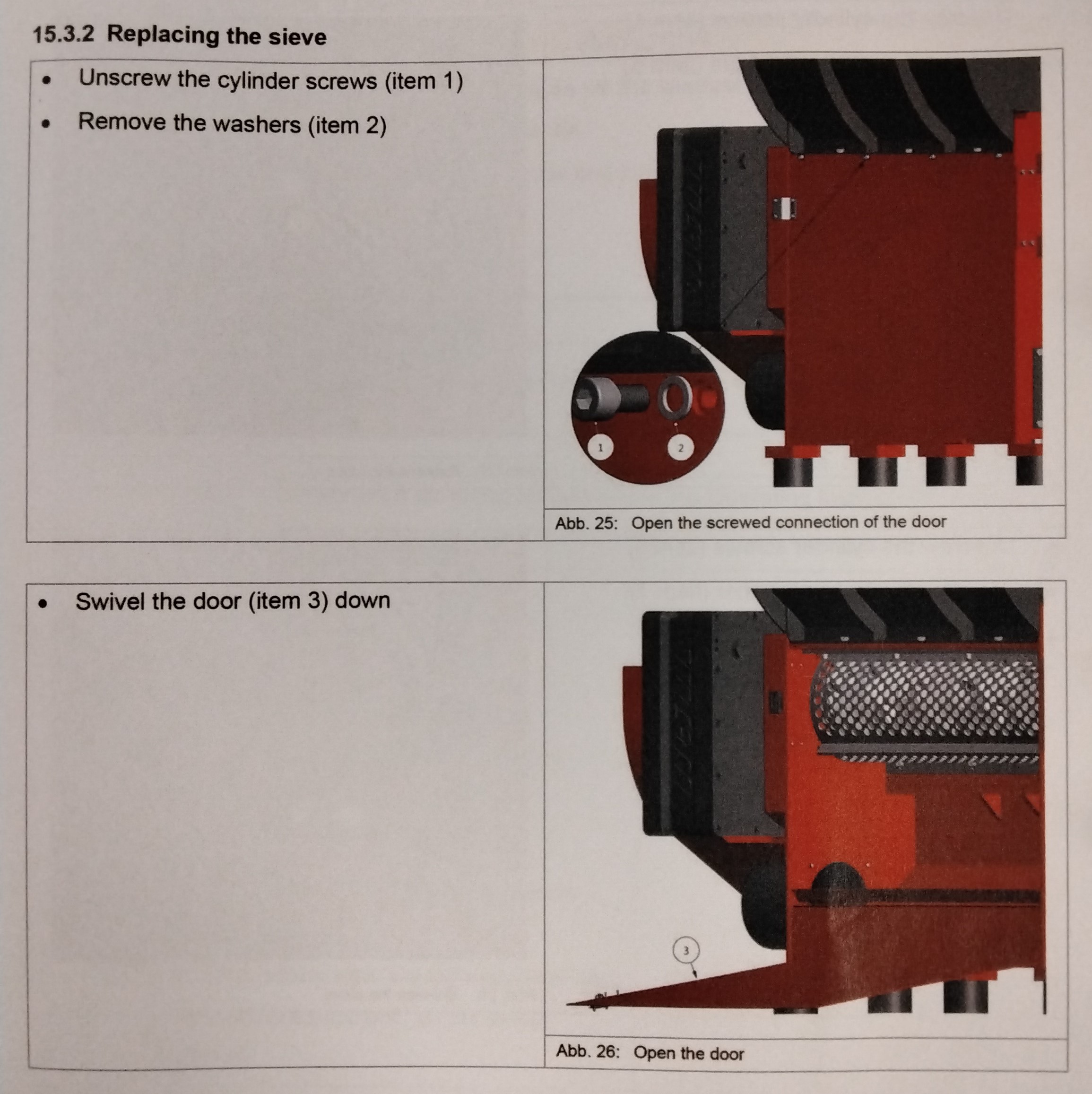
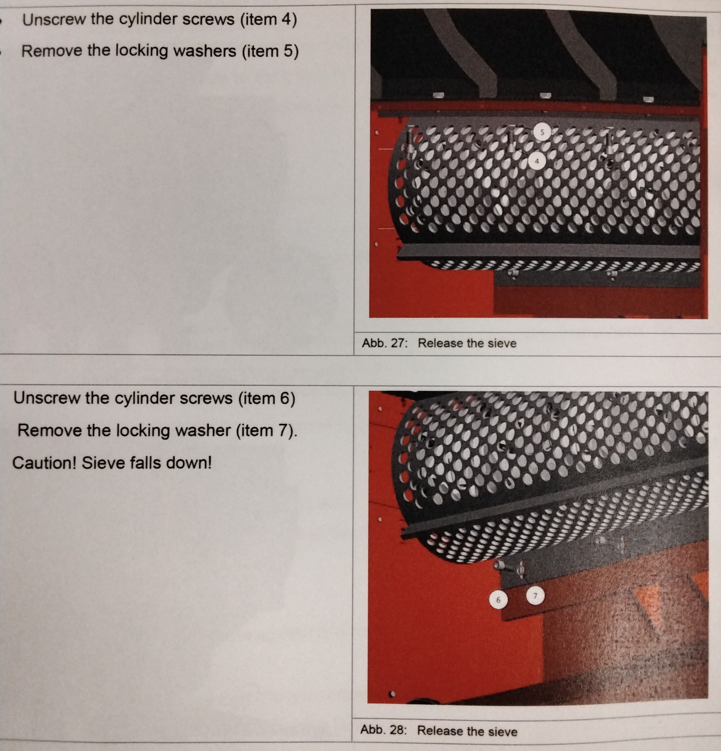
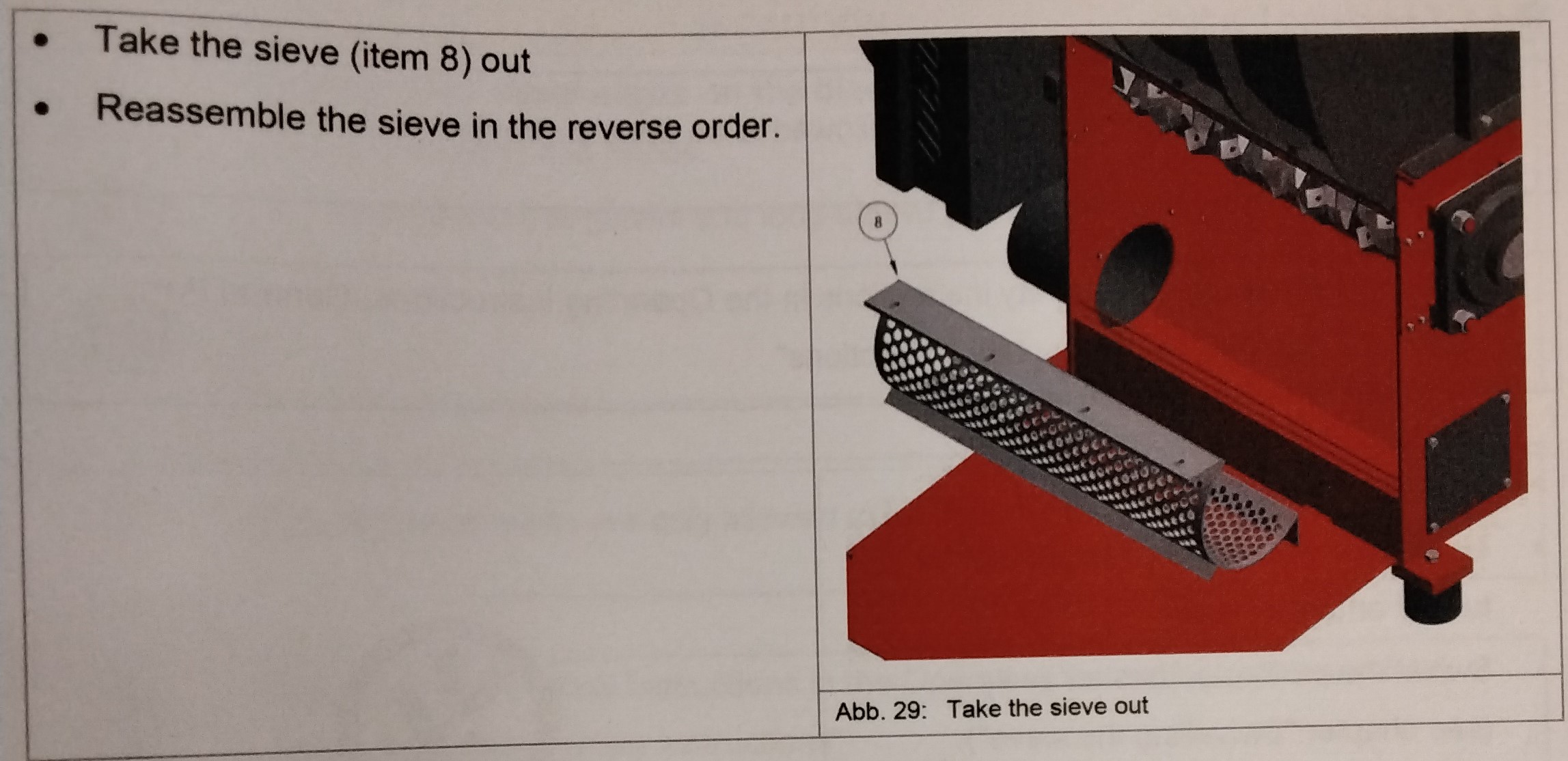
CAUTION: DANGER FROM SHARP EDGES ONT HE BLADES/ COUNTER BLADES (Cuts to arms and hands.) -Wear protective gloves and long-sleeve protective clothing. Maintenance works are only allowed to be done by trained personnel. Please find the safety instructions in the Operating Instruction, General Part, Chapter "General Safety Instructions" -Switch the rotor off ---The rotor runs down -Swivel the perforated basket away (see chapter "Replacement of Sieve") -Turn the machine off -Main switch off -Secure the machine against accidental switching on -Attach a safety sign "Do not switch on! Men working on equipment" on the switch cabinet. REPLACING THE SIEVE -Unscrew the cylinder screws (Item 1) -Remove the washers (Item2) -Swivel the door (Item 3) down. -Unscrew the cylinder screws (Item 4) -Remove the locking washers (Item 5) -Unscrew the cylinder screws (Item 6) -Remove the locking washer (Item 7) -Caution! Sieve falls down! -Take the sieve (Item 8) out. -Reassemble the sieve in the reverse order.
MAINTENANCE 5
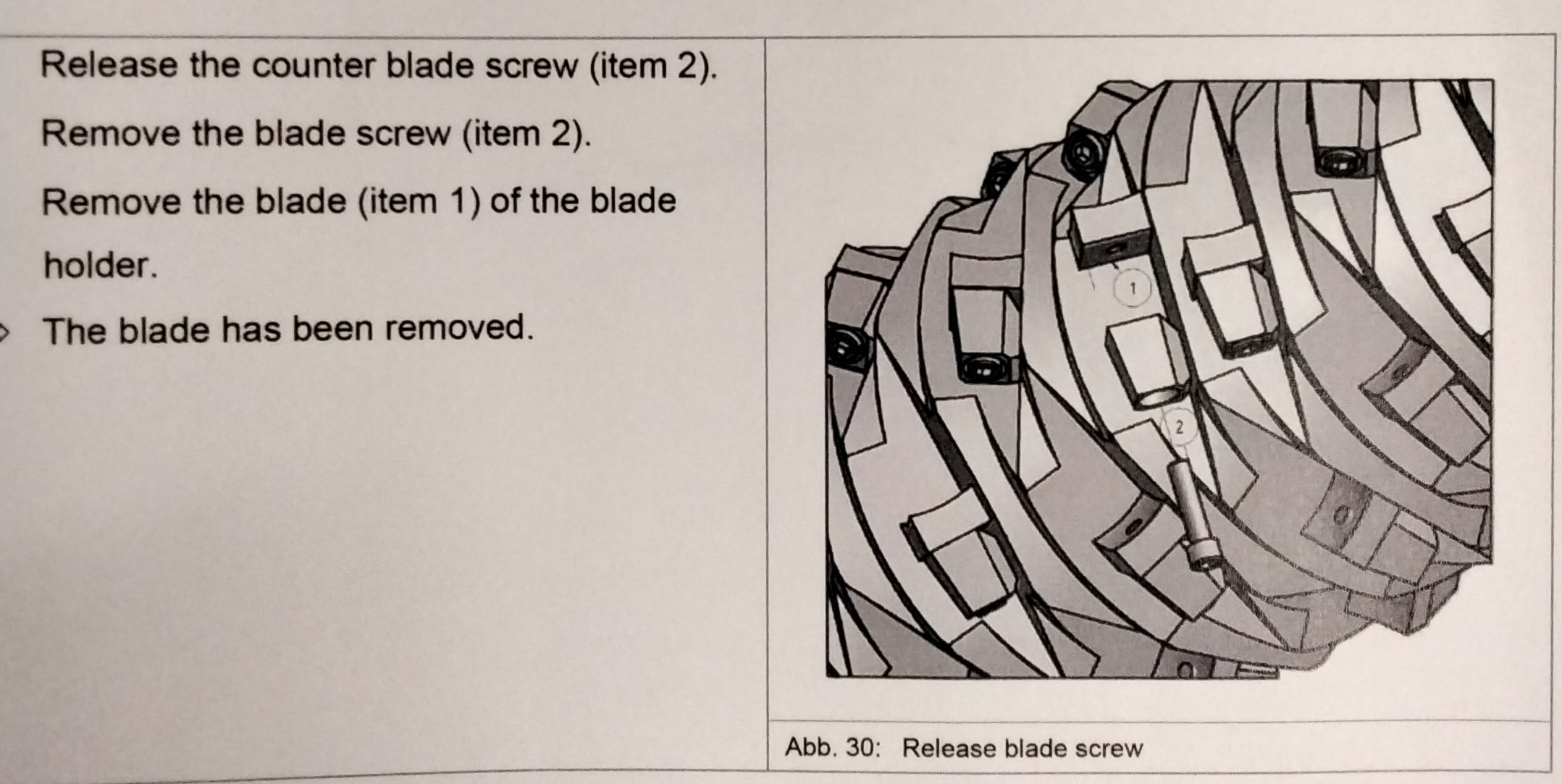
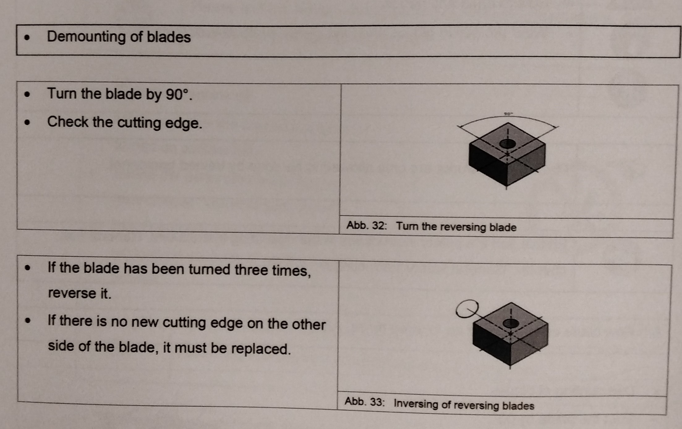
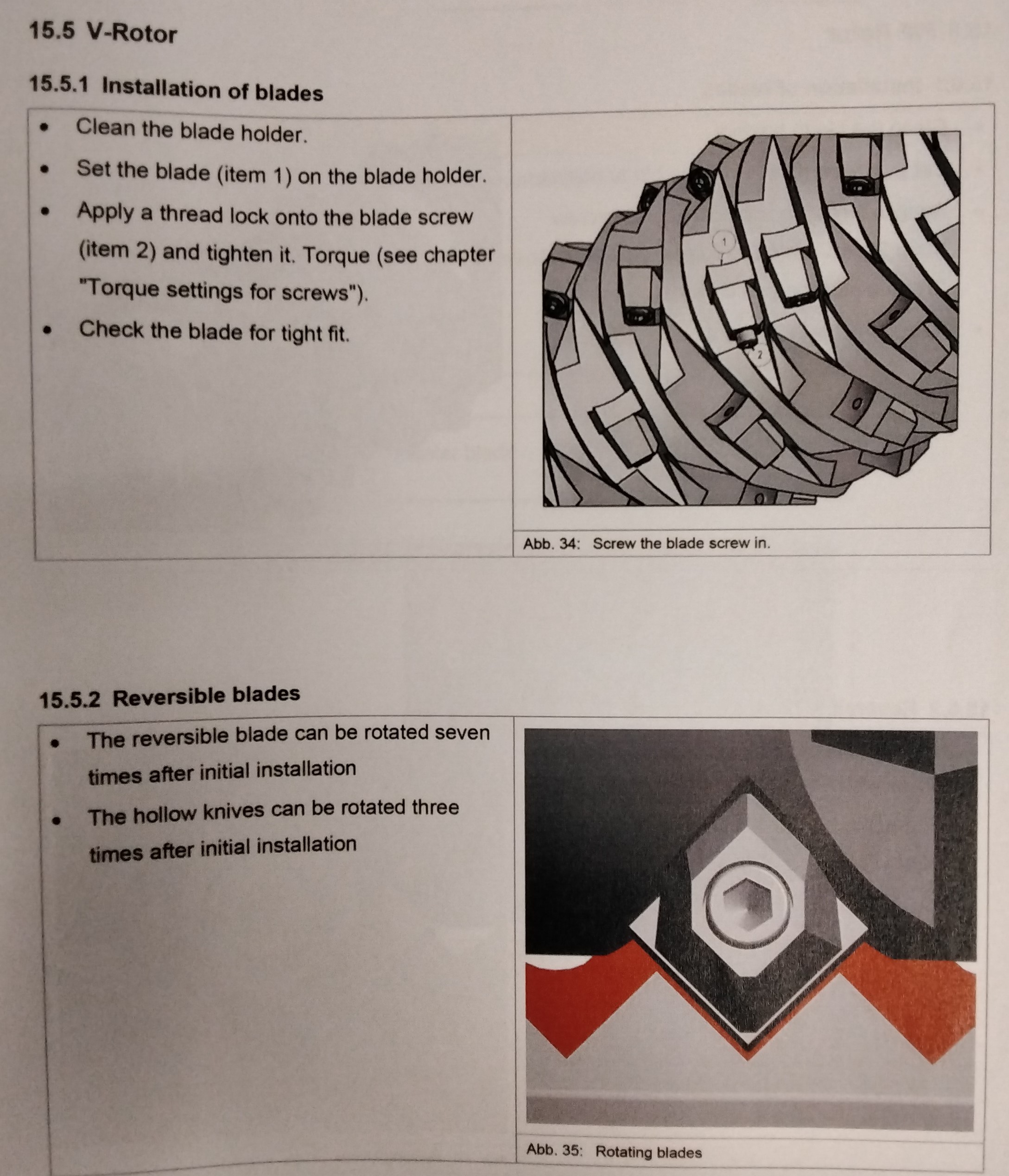
REPLACING OR INVERSING THE BLADES AND REMOVING BLADES Maintenance works are only allowed to be done by trained personnel. Please find the safety instructions in the Operating Instructions, General part, Chapter "General Safety Instructions" -Turn the machine off -Make sure that the machine cannot be turned on accidentally. -Swivel the perforated basket away (See Chapter, Swivelling the sieve) -Attach a safety sign "Do not switch on!" Men working on equipment" on the switch cabinet. REMOVING ENCRUSTATIONS ON THE HEXAGONAL BLADE SCREW -Release the counter blade screw (Item 2) -Remove the blade screw (Item 2) -Remove the blade (Item 1) of the blade holder. ---The blade has been removed TURNING HOLLOW BLADE DANGER from sharp edges on blades/counter blades. -Cuts to arms and hands -Wear protective gloves and long-sleeve protective clothing. Maintenance works are only allowed to be done by trained personnel. Please find the safety instructions in the Operating Instructions, General Part, chapter "General Safety Instructions" A hollow blade can be turned up to three times. After that, it must be replaced by a new one. -DEMOUNTING OF BLADES -Turn the blade by 90 degrees -Check the cutting edge. -After the blade was turned for three times, replace it. -Insertion of blade. TURNING OR REVERSING OF THE REVERSING BLADE A reversing blade can be turned three times. After that it can be reversed and turned another three times. After that it must be replaced by a new reversing blade. DEMOUNTING OF BLADES -Turn the blade 90 degrees -Check the cutting edge -If the blade has been turned three times, reverse it. -If there is no new cutting edge on the other side of the blade, it must be replaced. V-ROTOR INSTALLATION OF BLADES -Clean the blade holder. -Set the blade (Item 1) on the blade holder. -Apply a thread lock onto the blade screw. (Item 2) and tighten it. Torque (see Chapter "Torque settings for screws") -Check the blade for tight fit. REVERSIBLE BLADES -the reversible blade can be rotated seven times after initial installation. -The hollow knives can be rotated three times after initial installation.
MAINTENANCE 6
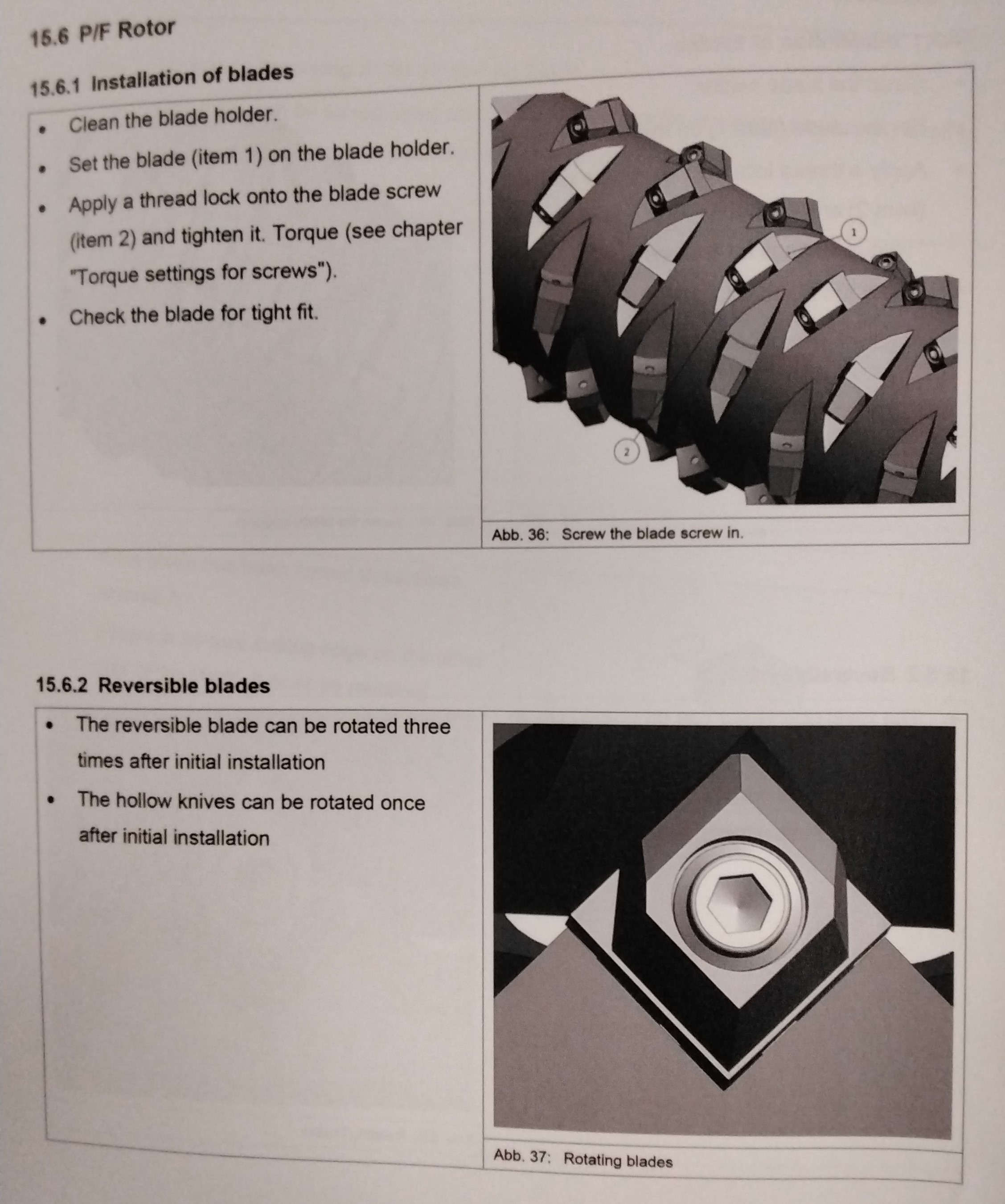
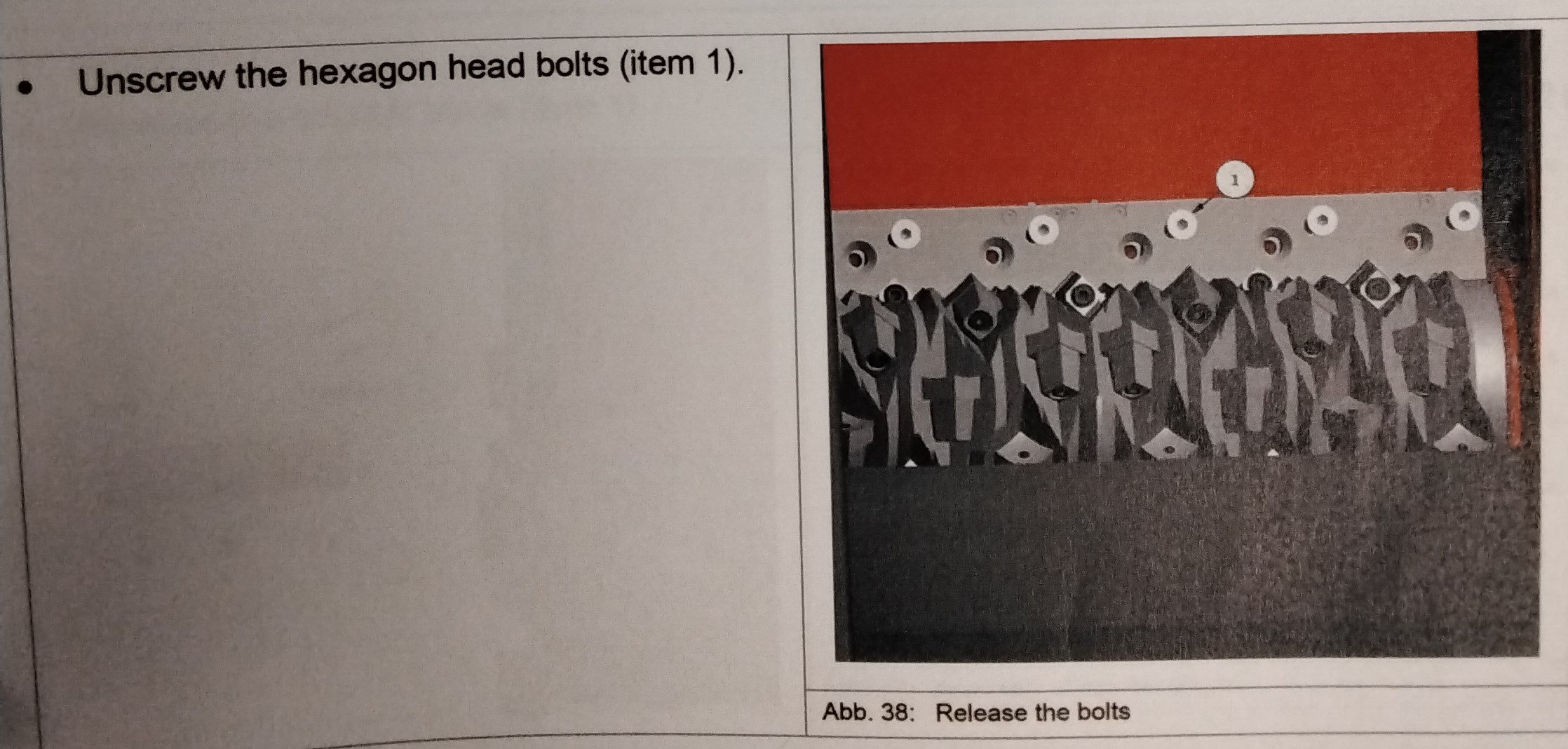
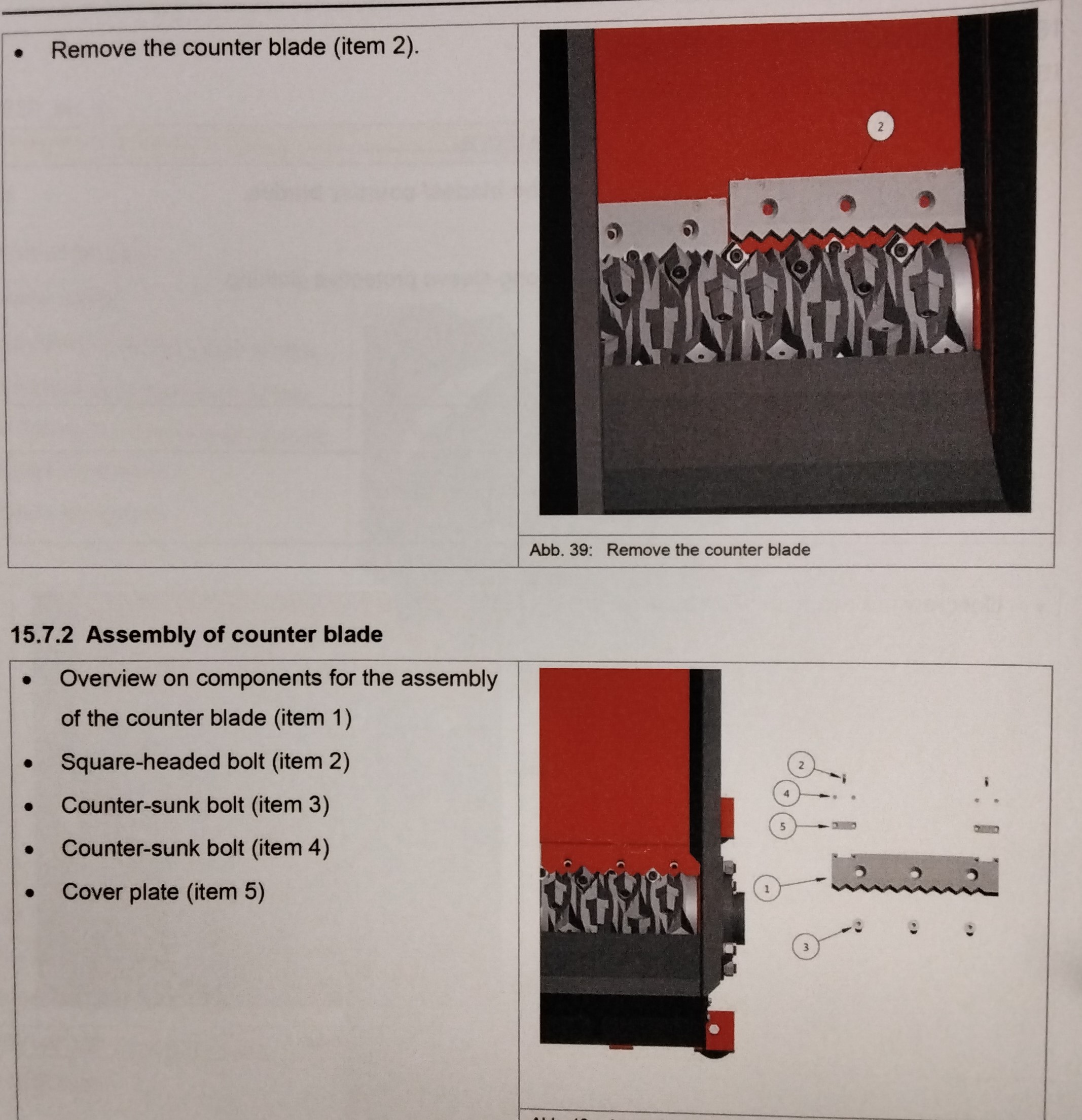
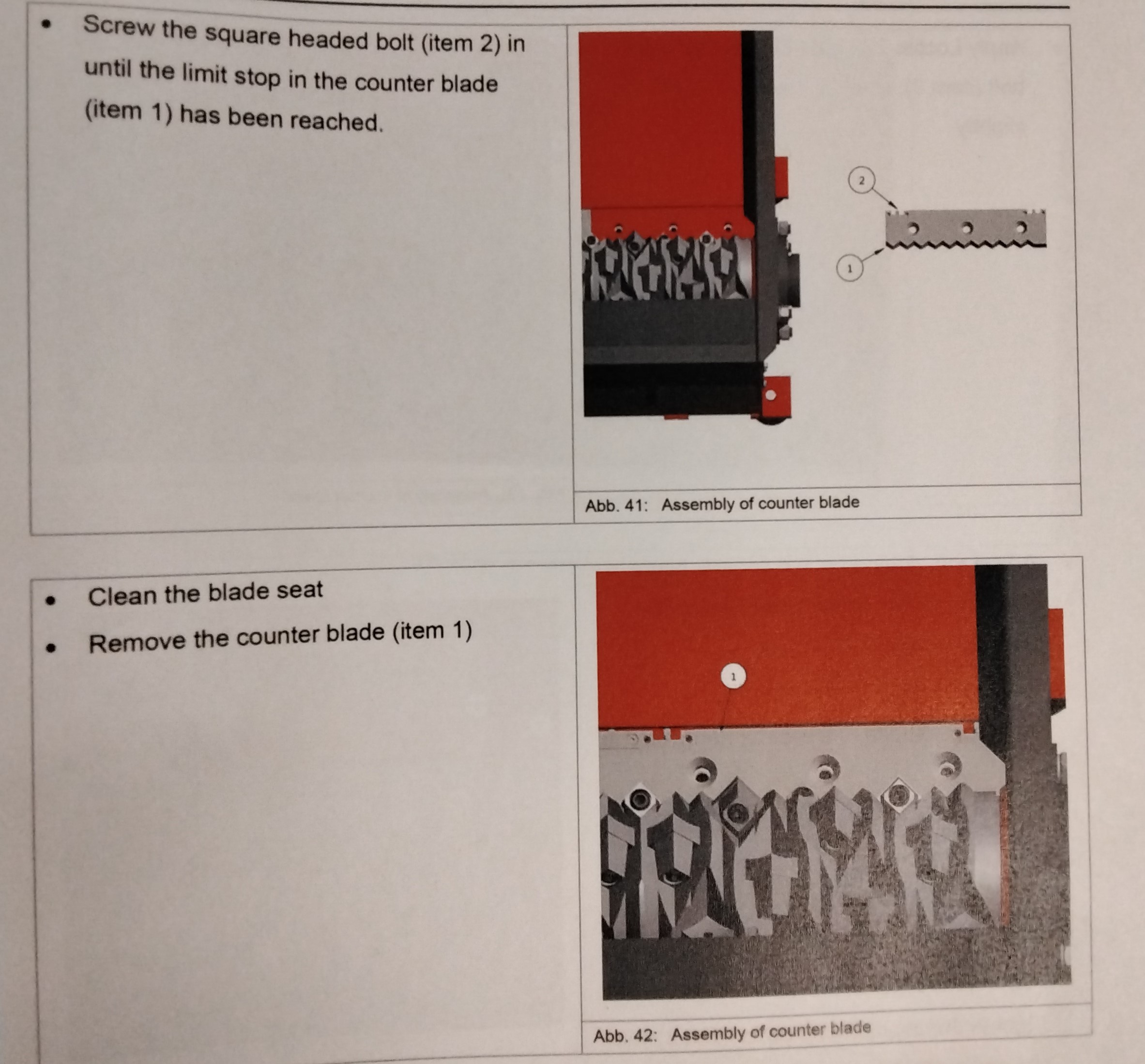
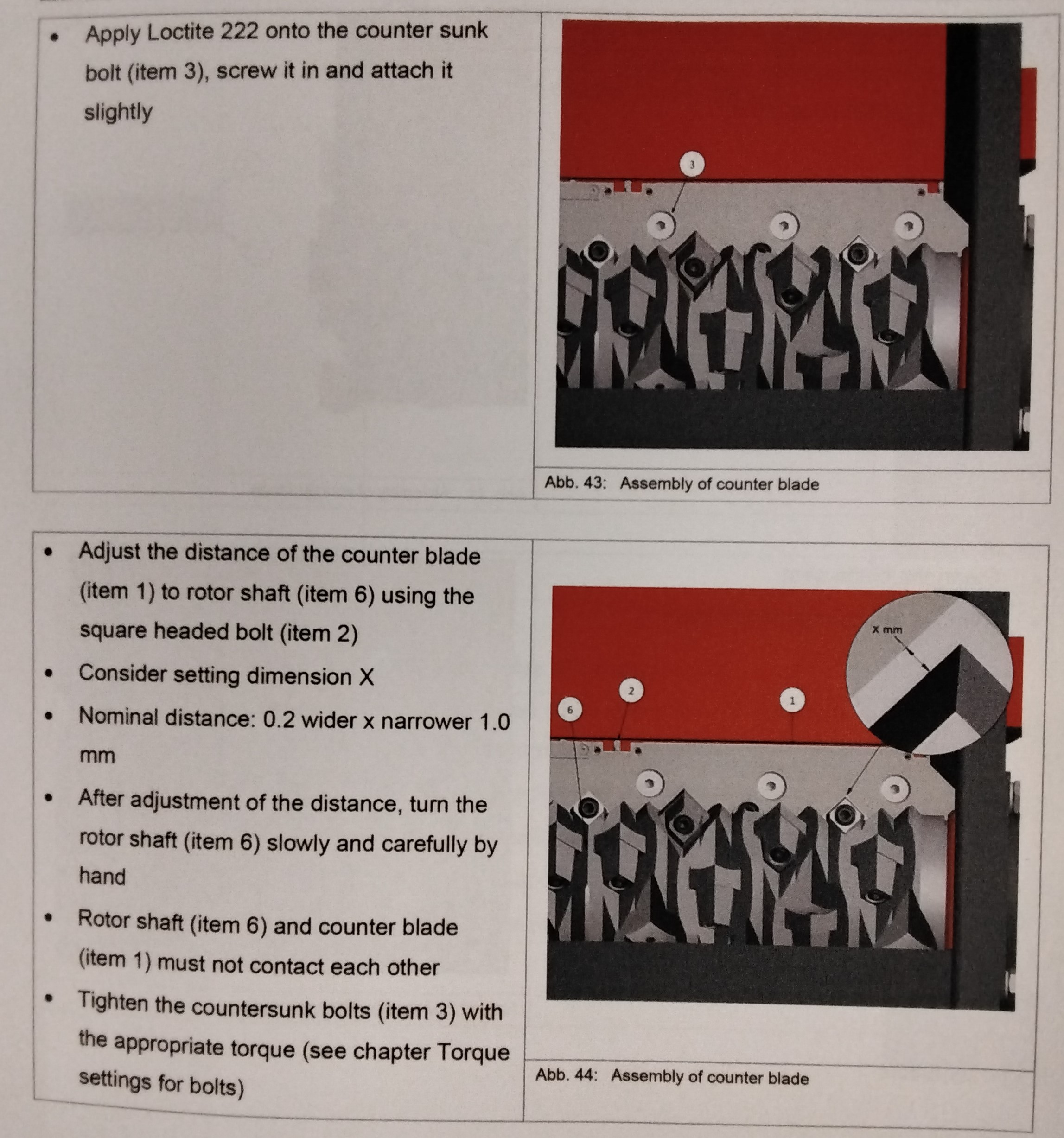
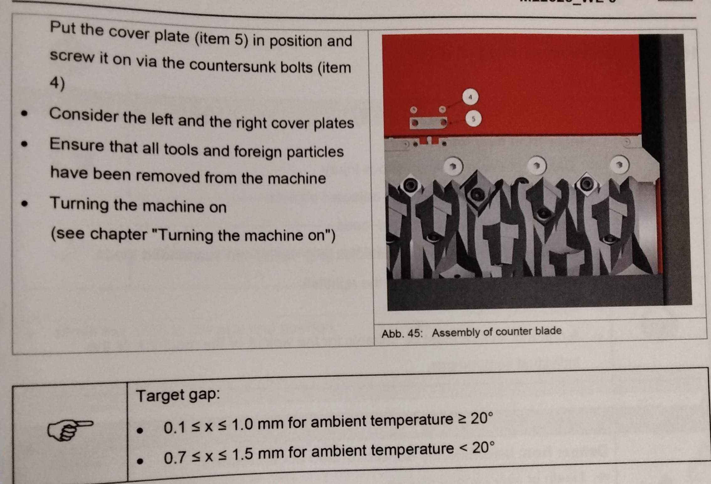
P/F ROTOR INSTALLATION OF BLADES -Clean the blade holder. -Set the blade (item 1) on the blade holder. -Apply a thread lock onto the blade screw (Item 2) and tighten it. Torque (See Chapter "Torque settings for screws") -Check the blade for tight fit. REVERSIBLE BLADES -the reversible blade can be rotated three times after initial installation. -The hollow knives can be rotated once after installation. REPLACEMENT OF COUNTER BLADE DISASSEMBLY OF COUNTER BLADE CAUTION! DANGER from sharp edges of the blades/counter blades. ---cut to arms and hands -Wear protective gloves and long-sleeve protective clothing. REMOVING OF ENCRUSTATIONS ON THE COUNTER BLADE - Unscrew the hexagon head bolts (Item1). REMOVE THE COUNTER BLADE ASSEMBLY OF COUNTER BLADE -Overview on components for the assembly of the counter blade (Item 1) -Square-headed bolt (Item2) -Counter-sunk bolt (Item3) -Counter sunk bolt (Item 4) -Cover plate (Item5) -Screw the square headed bolt (Item2) in until the limit stop in the counter blade (Item1) has been reached. -Clean the blade seat -Remove the counter blade (Item 1) -Apply Loctite 222 onto the counter sunk bolt (Item3), screw it in and attach it slightly. -Adjust the distance of the counter blade (Item 1) to rotor shaft (Item 6) using the square headed bolt (Item2) -Consider setting dimension X -Nominal distance: 0.2 wider x narrower 1.0 mm -After adjustment of the distance, turn rotor shaft (Item 6) slowly and carefully by hand. -Rotor Shaft (Item 6) and counter blade (Item1) must not contact each other. -Tighten the countersunk bolts (Item 3) with the appropriate torque (See Chapter Torque settings for bolts) Put the cover plate (Item 5) in position and screw it on via the countersunk bolts (Item 4) -Consider the left and the right cover plates -Ensure that all tools and foreign particles have been removed from the machine. -Turning the machine on (see Chapter "Turning on the Machine")
MAINTENANCE 7
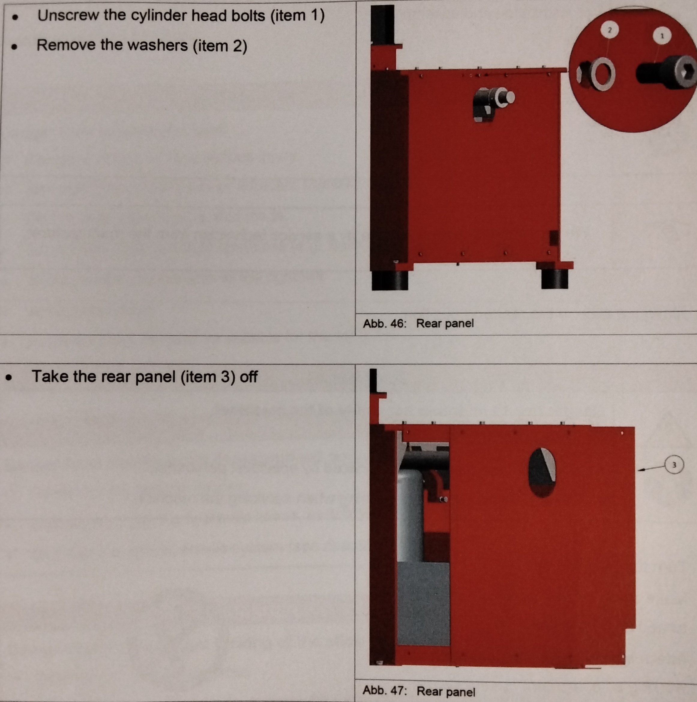
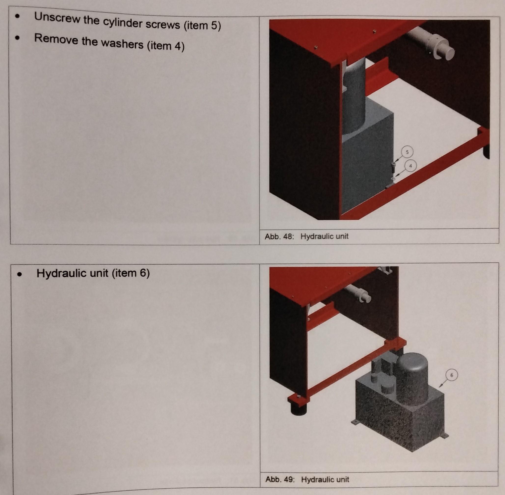
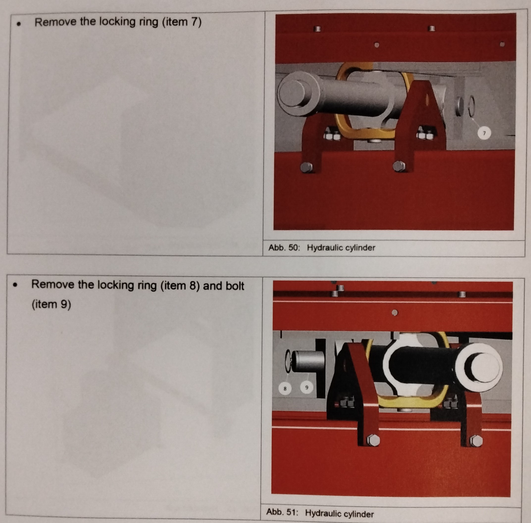
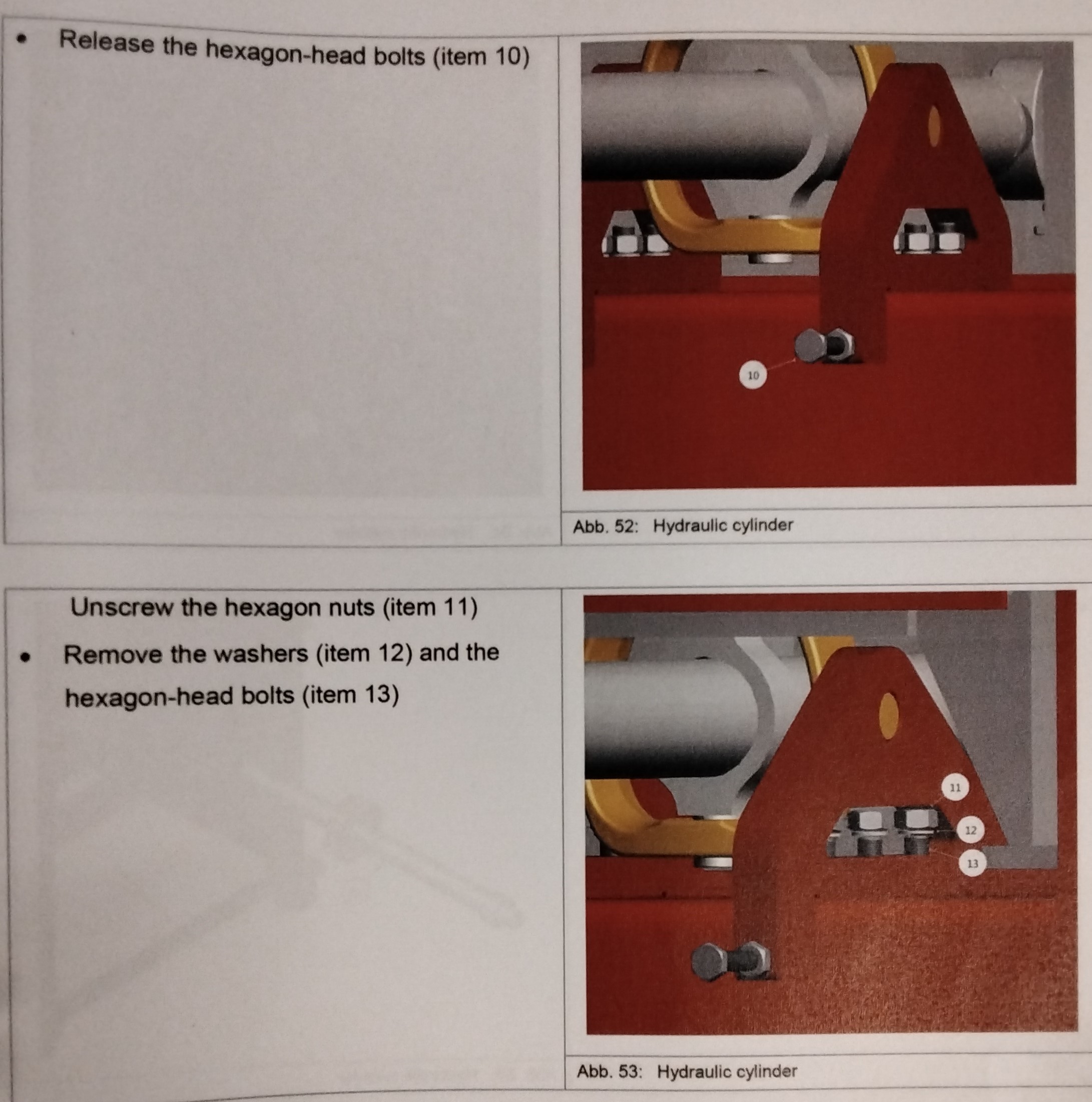
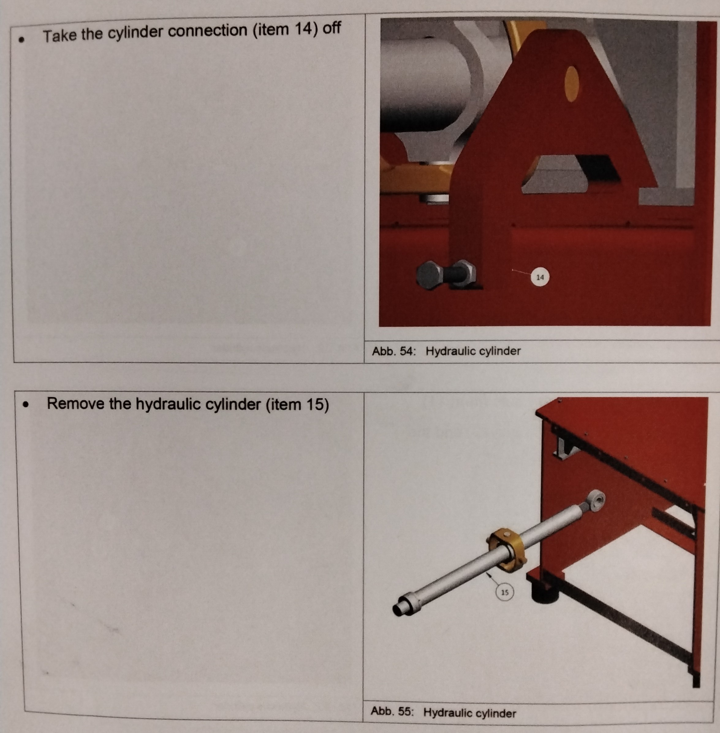
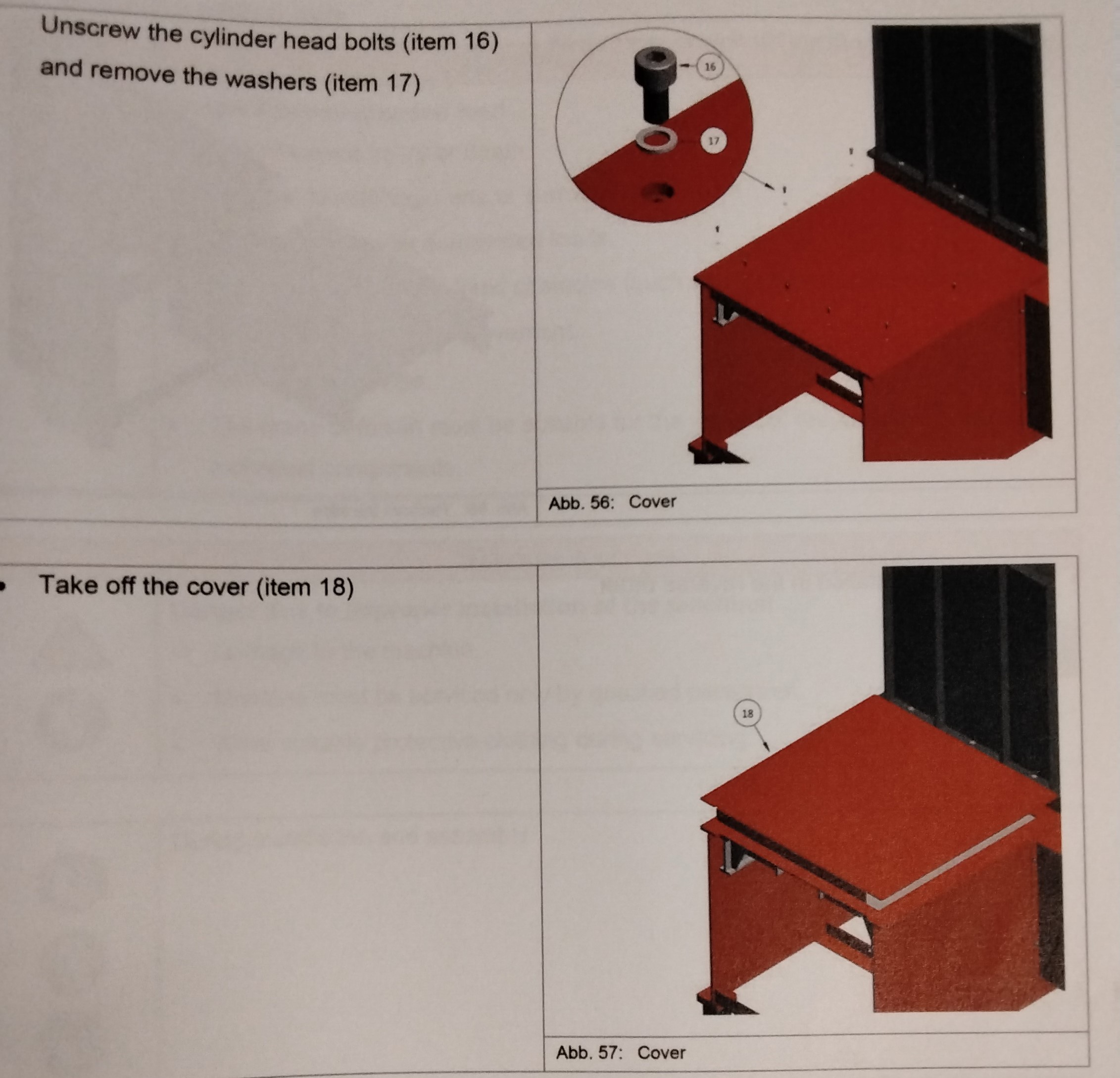
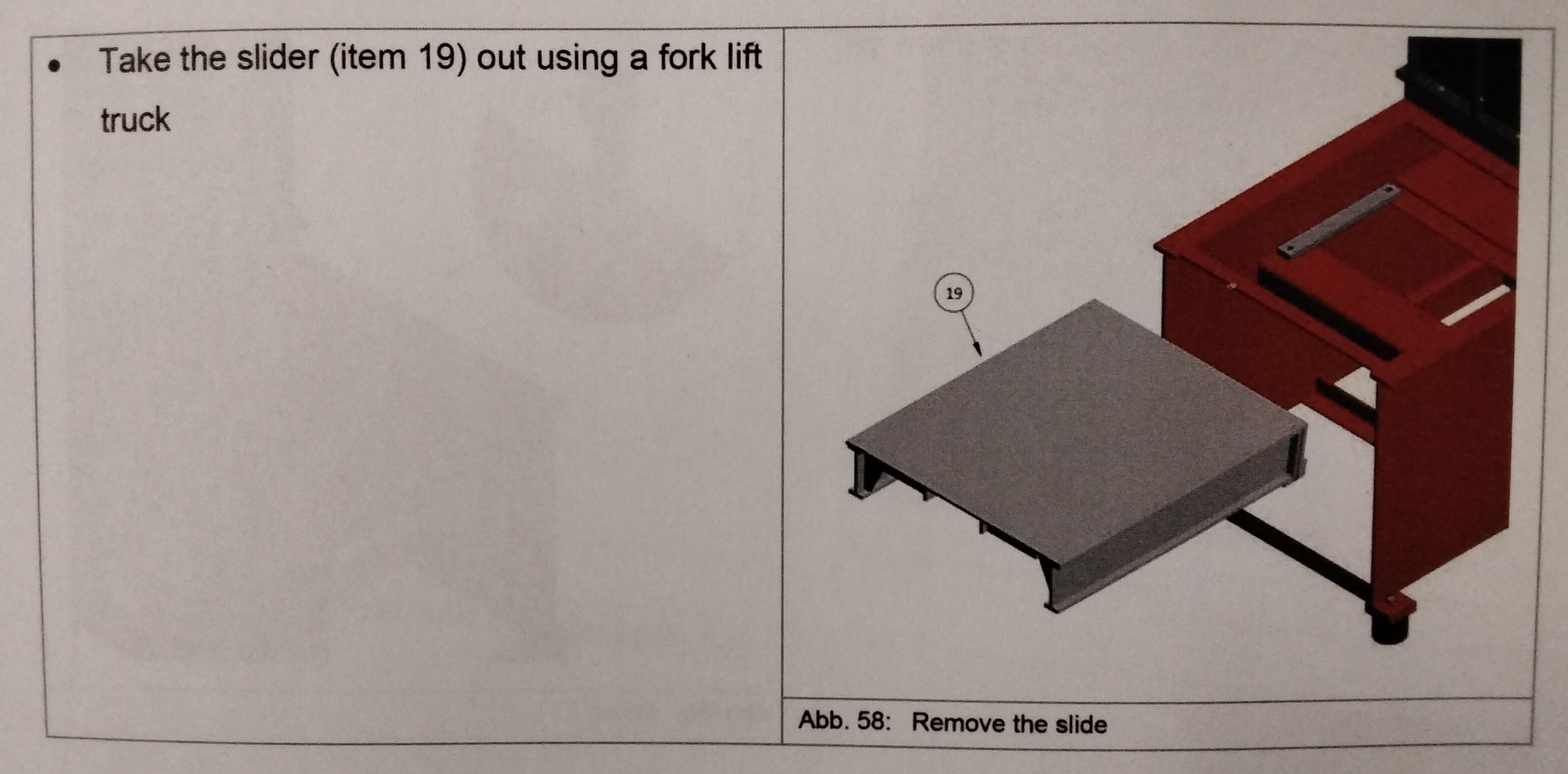
DANGER FROM SUSPENDED LOAD: ---Danger of death or very serious injury ---Damage to machine parts or adjacent objects. -Do not step under suspended loads. -Do not step between rigid obstacles (e.g. walls) and suspended loads. -Avoid sudden movements to the right/ left. -Avoid jerky stops. -a crane or fork lift must be suitable for the weight of the machine or the individual components. DANGER FROM INSUFFICIENTLY DEPRESSURIZED ACCUMULATORS ---Death or very serious injuries -Before removing the hydraulic hoses, switch the hydraulic unit off. -Depressurize the hydraulic system (See Chapter "Hydraulic Unit") DANGER DUE TO INSUFFICIENT LOCKING OF THE SLIDE ---Death or very serious injures. -The crane or fork lift must be suitable for the weight of the machine or the individual components. FOR INSTALLATION AND ASSEMBLY -We recommend replacing done by a service technician from the manufacturer. -Move the slide to the rear end position. WARNING! ---DANGER DUE TO IMPROPER ASSEMBLY OF MACHINE! --Damage to the machine -The machine may only be serviced by specialist personnel. -Wear suitable protective clothing when servicing the machine. -Turn the machine off -Make sure that the machine cannot be turned on accidentally. -Attach a safety sign "Do not switch on! Men working on equipment" on the switch cabinet. -Unscrew the cylinder head bolts (Item 1) -Remove the washers (Item 2) -Take the rear panel (Item 3) off -Unscrew the cylinder screws (Item 5) -Remove the washers -Hydraulic unit (Item 6) -Remove the locking ring (Item7) -Remove the locking ring (Item 8) and bolt (Item 9) -Release the hexagon-head bolts (Item 10) -Unscrew the hexagon nuts (Item 11) -Remove the washers (Item 12) and the hexagon-head bolts (Item 13) -Take the cylinder connection (Item 14) off -Remove the hydraulic cylinder (Item 15) -Unscrew the cylinder head bolts (Item 16) and remove the washers (Item 17) -Take off the cover (Item 18) -Take the slider (Item 19) out using a fort lift truck. -The slide is installed in the reverse order.
MAINTENANCE 8
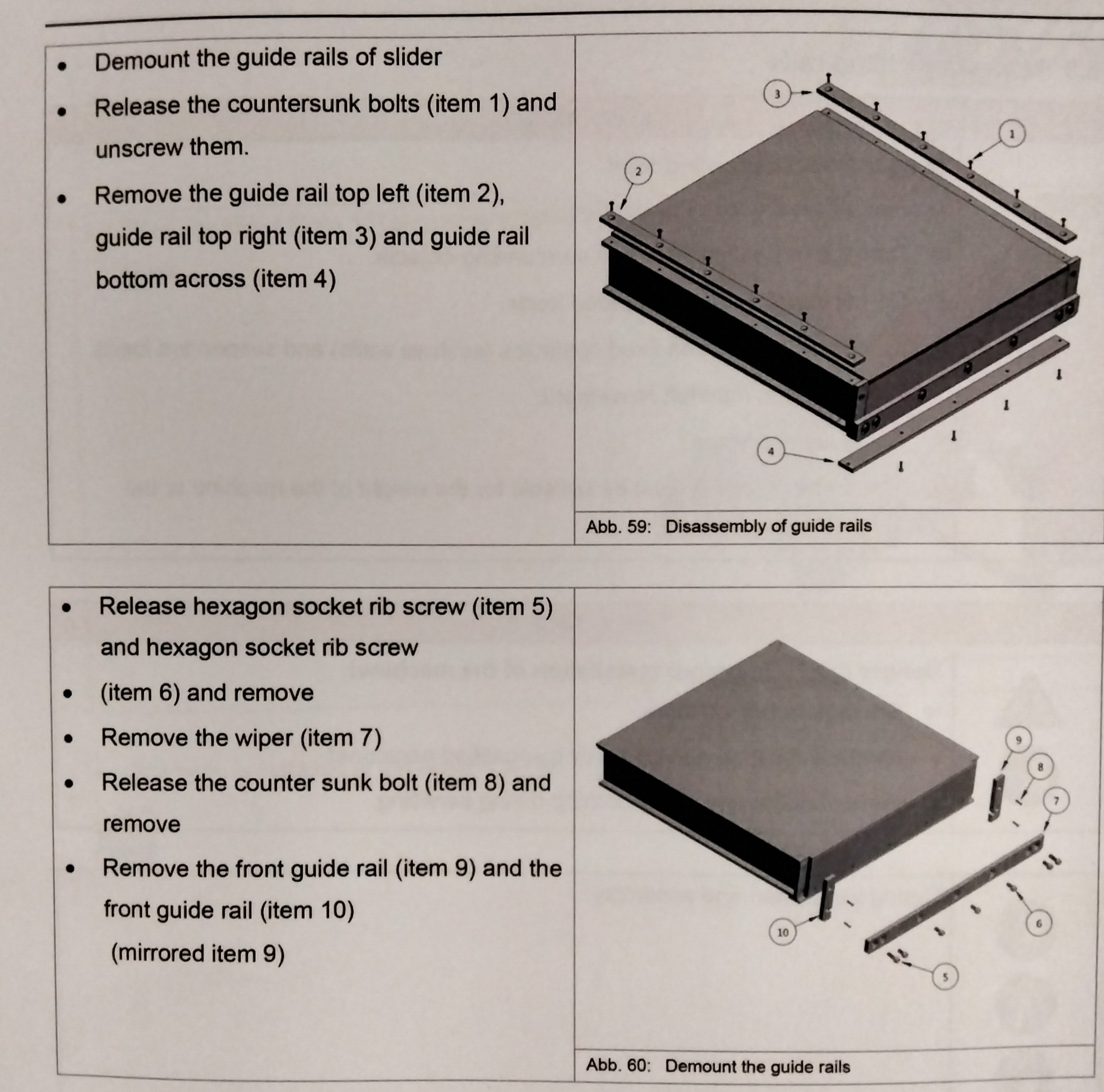
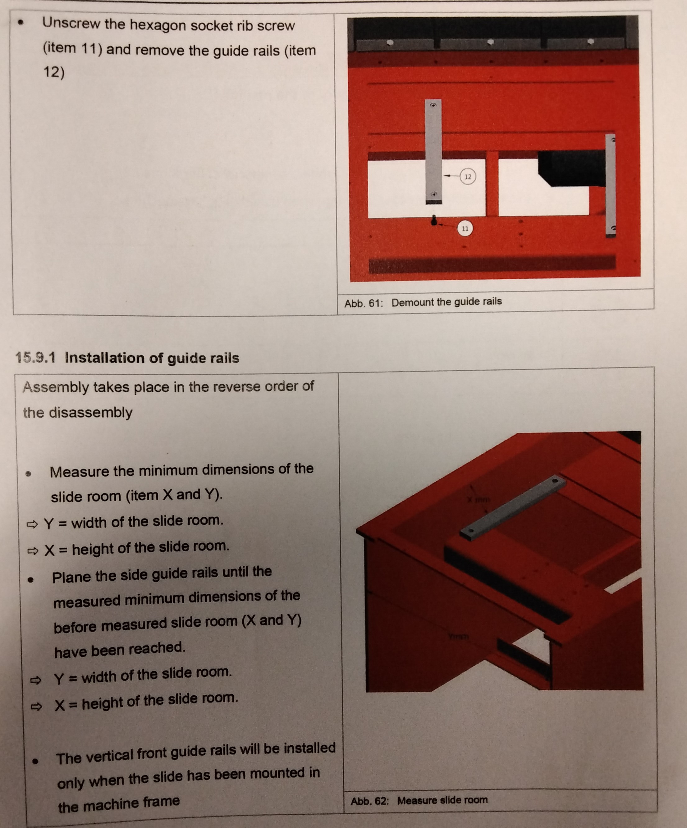
WARNING! DANGER FROM SUSPENDED LOAD! ---Risk of severe injury or death. ---Damage to machine parts or surrounding objects. -Do not stand under suspended loads -Do not stand between fixed obstacles (such as walls) and suspended loads. -Avoid right/left movement. -Avoid sudden stops -The crane or forklift must be suitable for the weight of the machine or individual components. WARNING! DANGER DUE TO IMPROPER INSTALLATION OF THE MACHINE! ---Damage to the machine -Machine must be serviced only by qualified personnel. -Wear suitable protective clothing during servicing. DURING INSTALLATION AND ASSEMBLY -We recommend the replacement by a service technician of the manufacturer. -Demount the guide rails of slider -Release the countersunk bolts (Item1) and unscrew them. -Remove the guide rail top left (Item 2), guide rail top right (Item 3) and guide rail bottom across (Item 4). -Release hexagon socket rib screw (Item 5) and hexagon socket rib screw -(Item 6) and remove. -Remove the wiper (Item 7) -Release the counter sunk bolt (Item 8) and remove. -Remove the front guide rail (Item 9) and the front guide rail (Item 10) -(mirrored Item 9) -Unscrew the hexagon socket rib screw (Item 11) and remove the guide rails (Item 12)
MAINTENANCE 9
Assembly takes place in the reverse order of disassembly. -Measure the minimum dimensions of the slide room (Item X and Y) Y= width of the slide room X= Height of the slide room -Plane the side guide rails until the measured minimum dimensions of the before measured slide room (X and Y) has been reached. Y= width of the slide room X= height of the slide room -Vertical front guide rails will be installed only when the slide has been mounted in the machine frame.
MAINTENANCE 10
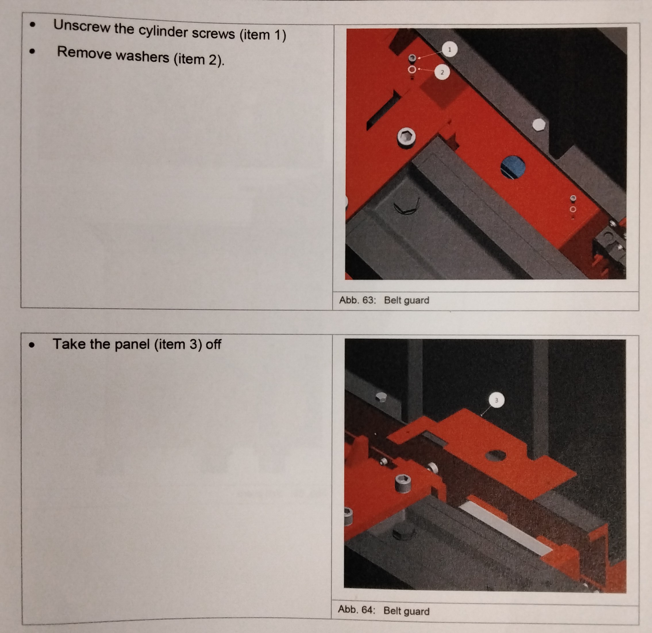
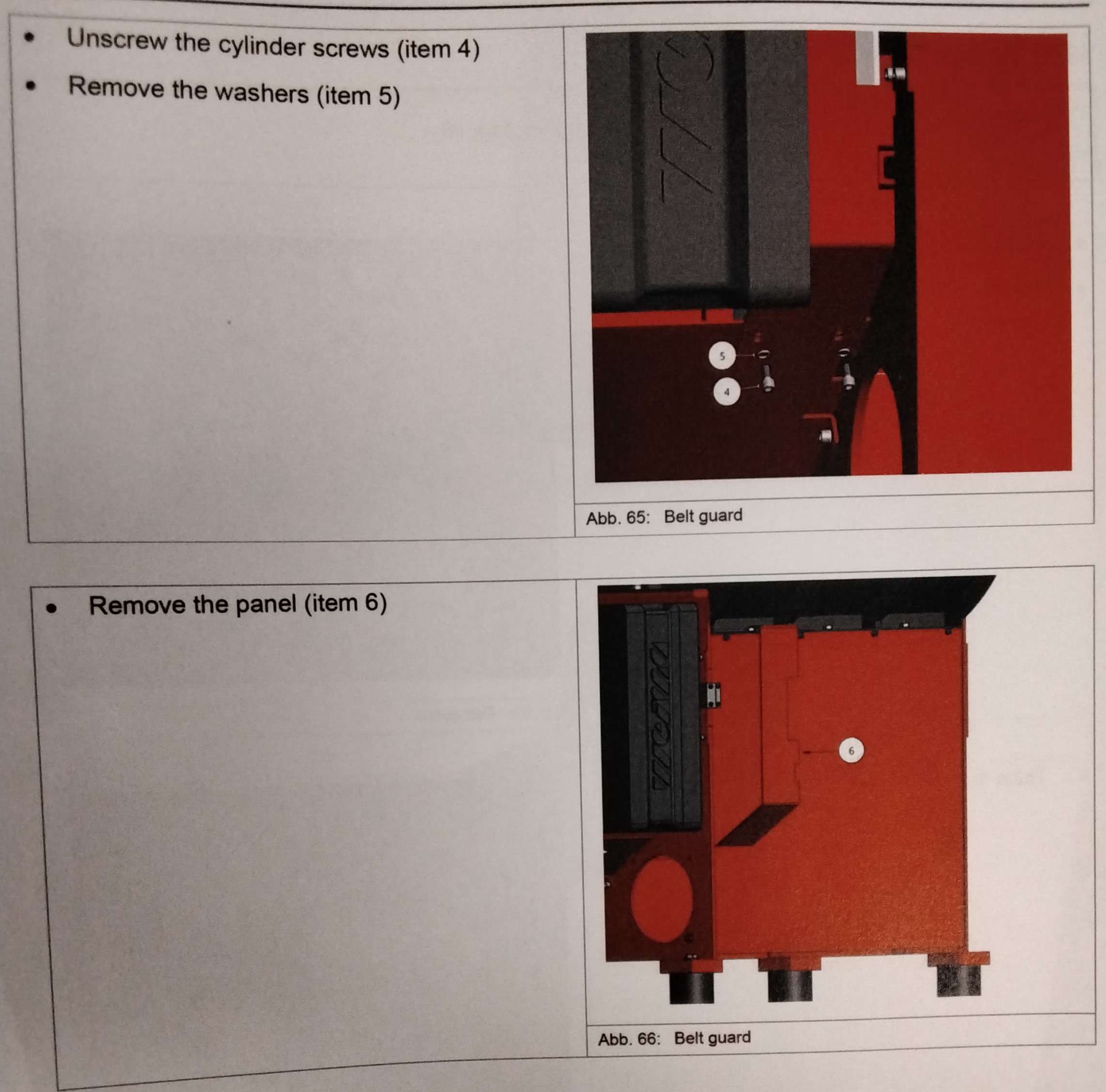
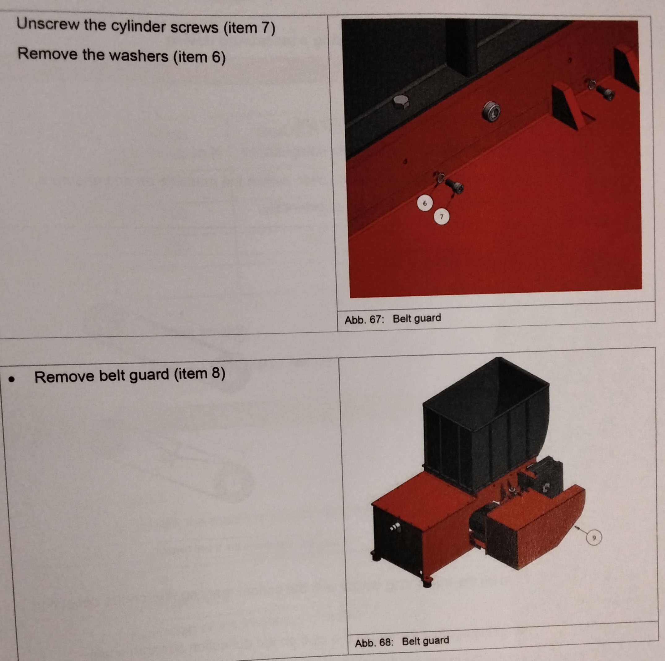
WARNING! DANGER DUE TO IMPROPER ASSEMBLY OF THE MACHINE! ---Damage to the machine ---Damage to the V-belt. -The machine may only be assembled by specialist personnel. -Wear suitable protective clothing when assembling the machine. REMOVING THE BELT GUARD -Turn the machine off. -Make sure that the machine cannot be turned on accidentally -Attach a safety sign "Do not switch on! Men working on equipment" on the switch cabinet" Secure the belt guard using a crane or fork lift. -Unscrew the cylinder screws (Item1) -Remove washers (Item 2) -Take the panel (Item 3) off -Unscrew the cylinder screws (Item 4) -Remove the washers (Item 5) -Remove the panel (Item 6) -Unscrew the cylinder screws (Item 7) -Remove the washers (Item6) -Remove the belt guard (Item 8)
MAINTENANCE 11
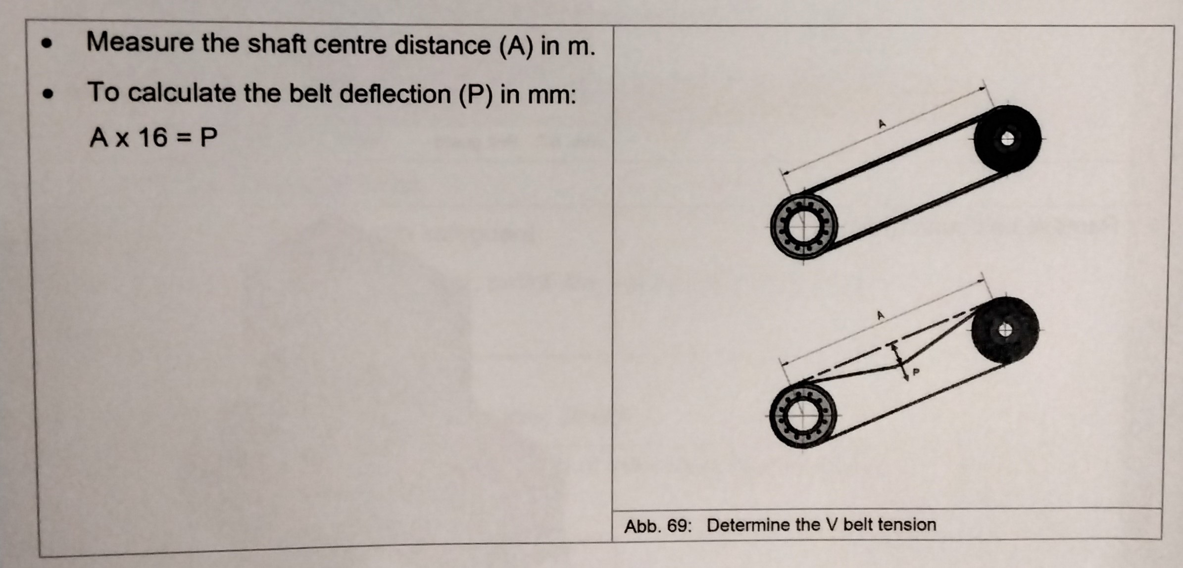
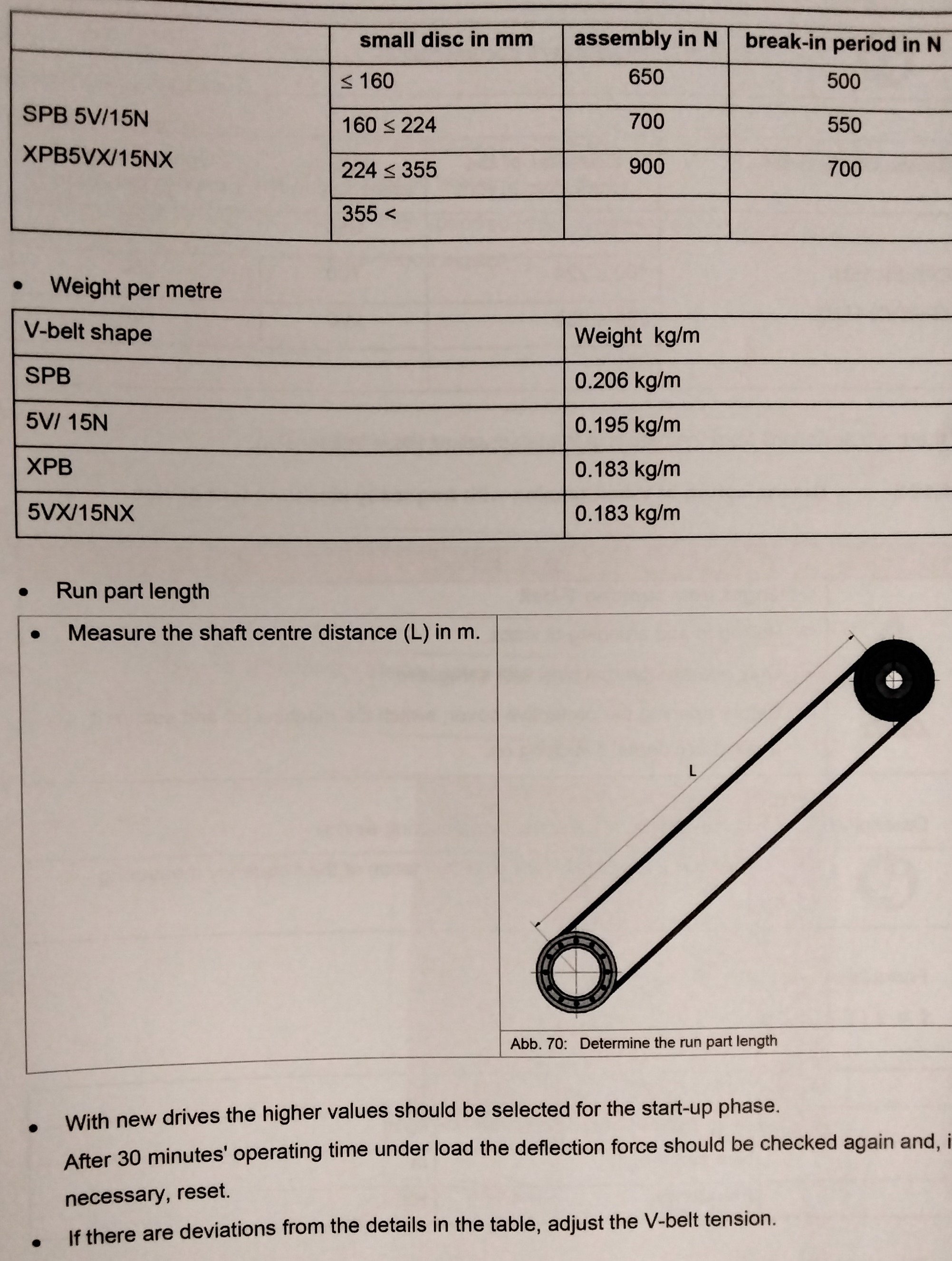
Determining V-Belt Tension using a measuring Device. DANGER FROM RUNNING THE V-BELT! ---Entanglement and crushing of limbs -Only operate the machine with safeguard -Before opening the protective cover, switch the machine off and ensure it cannot be switched on again accidentally. -Measure the shaft center distance (A) in m -To calibrate the belt deflection (P) in mm: A x 16 = P -Set the deflection on the measuring device with the bottom marking ring on the deflection scale in mm. -Place the top marking ring against the end of the pipe on the deflection strength scale. -Place the measuring device in the middle of the center distance at right angled to the belt. -Press on the top casing ---The belt will be pushed through. ---The force applied will be such that the selected deflection is reached. -Read off the deflection force at the location of the marking ring. -Compare the deflection force with the values in the table. ---With new drives the higher values should be selected for the start up phase. After 30 minutes operating time under load the deflection force should be checked again and, if necessary, reset. DETERMINATION OF V-BELT TENSION WITH FREQUENCY MEASUREMENT DEVICE WARNING! -DANGER FROM RUNNING THE V-BELT -Pulling in an crushing of limbs -Only operate the machine with safeguard -Before opening the protective cover, switch the machine off and secure it against accidental switching on. -Determine the V-Belt tension using a frequency measuring device. -Observe the manufacturer's documentation of the frequency measuring device.
MAINTENANCE 12
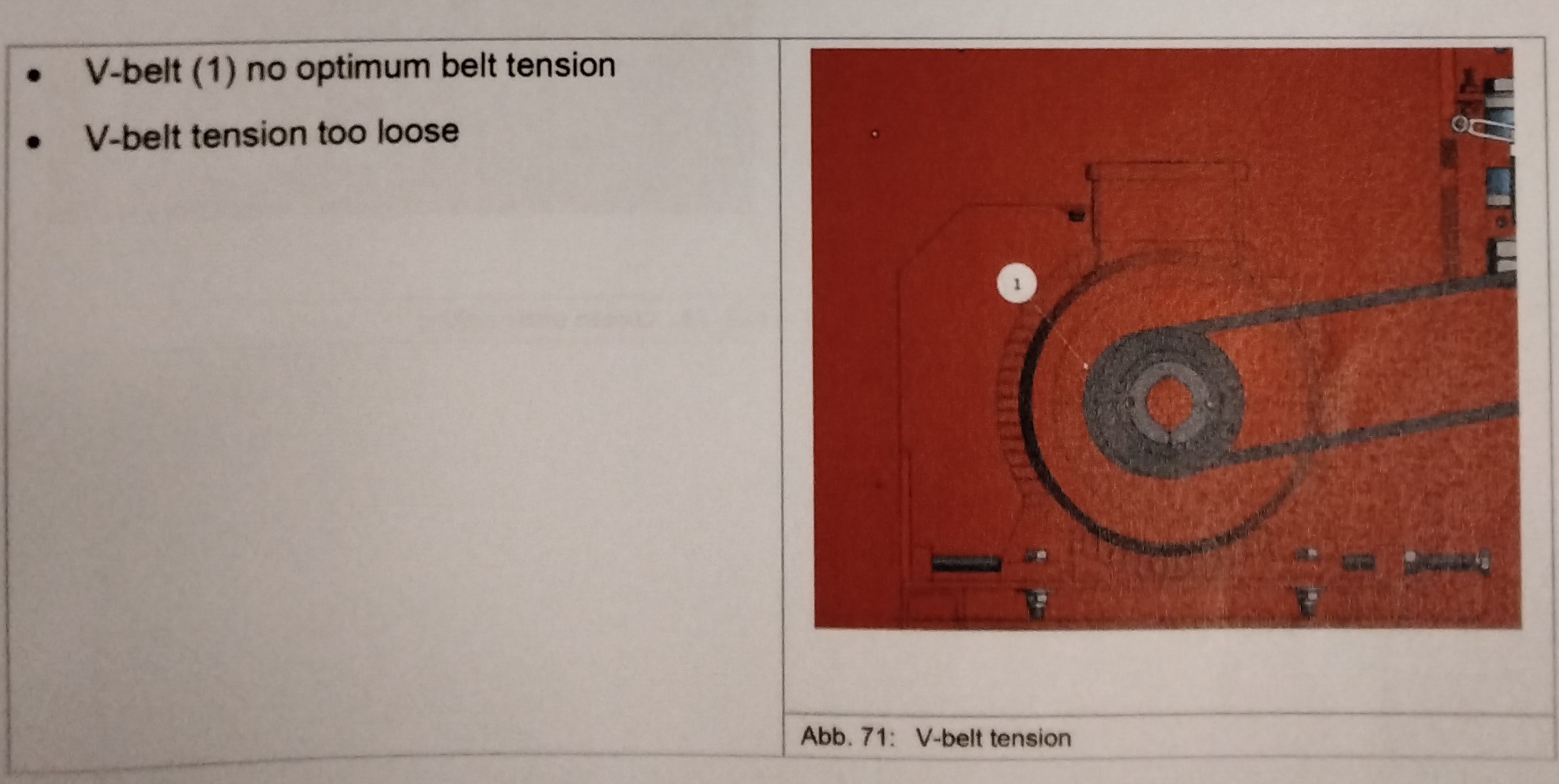
-Determine the V belt tension. -If measured deflection force is lower than specified in the table, the V-belt tension must be increased (see Chapter "Determining the V-belt Tension") -If measured deflection force is higher than specified in the table, the V-Belt tension must be decreased (see Chapter "Determining V-Belt Tension.")
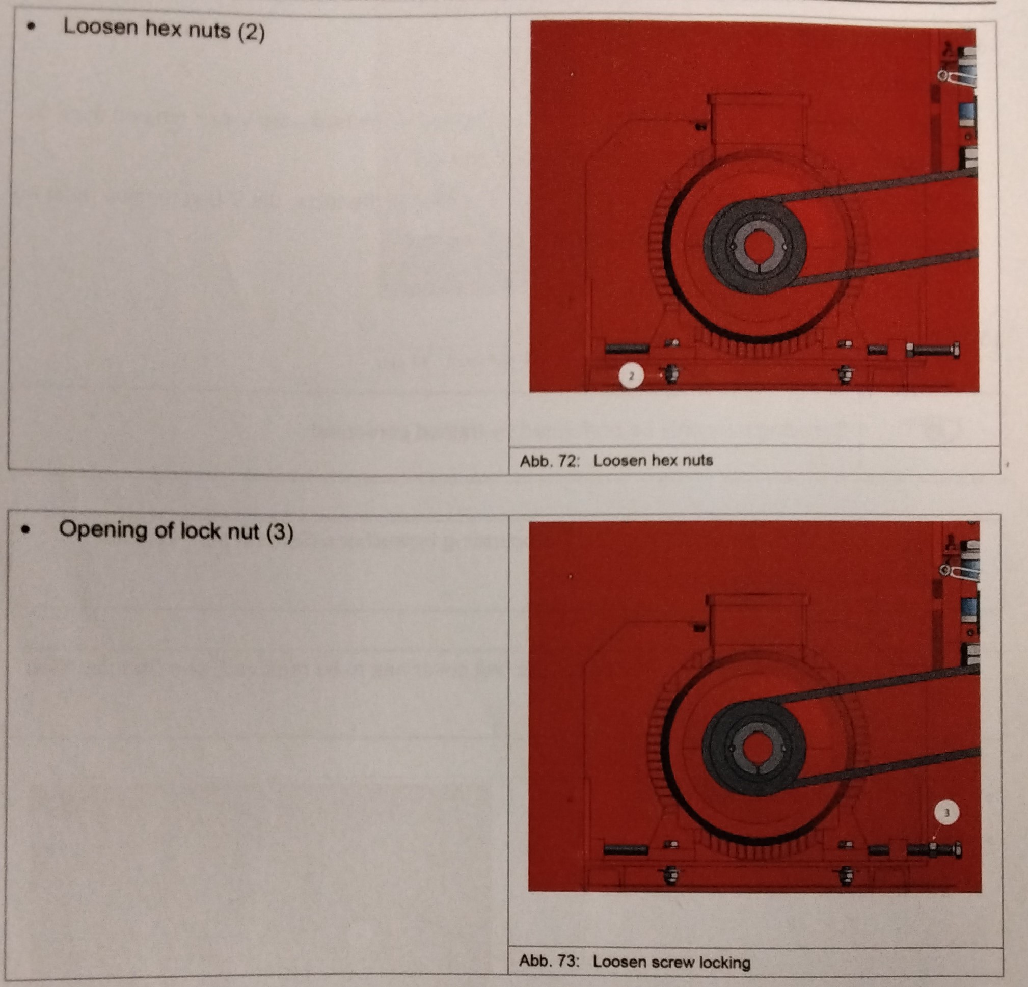
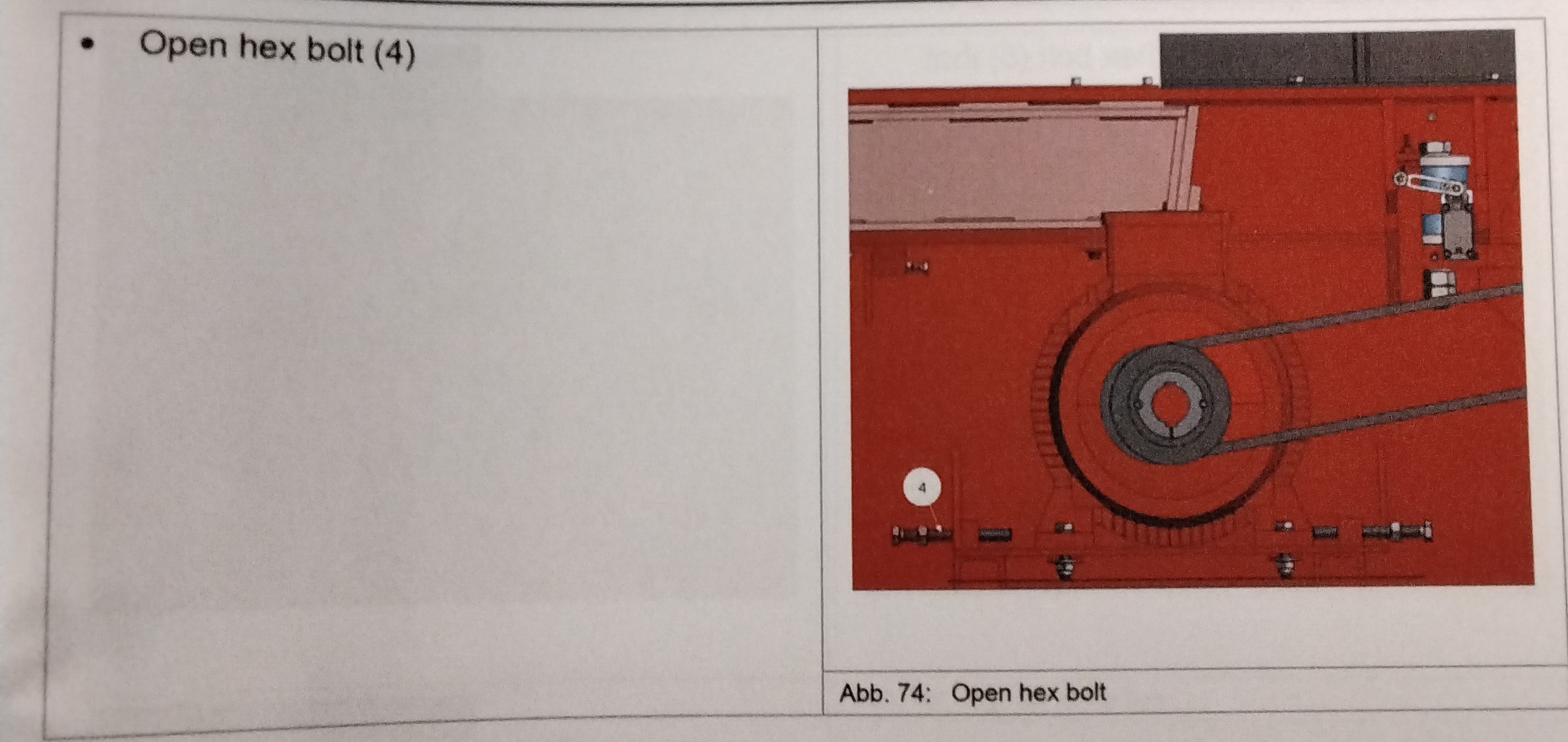
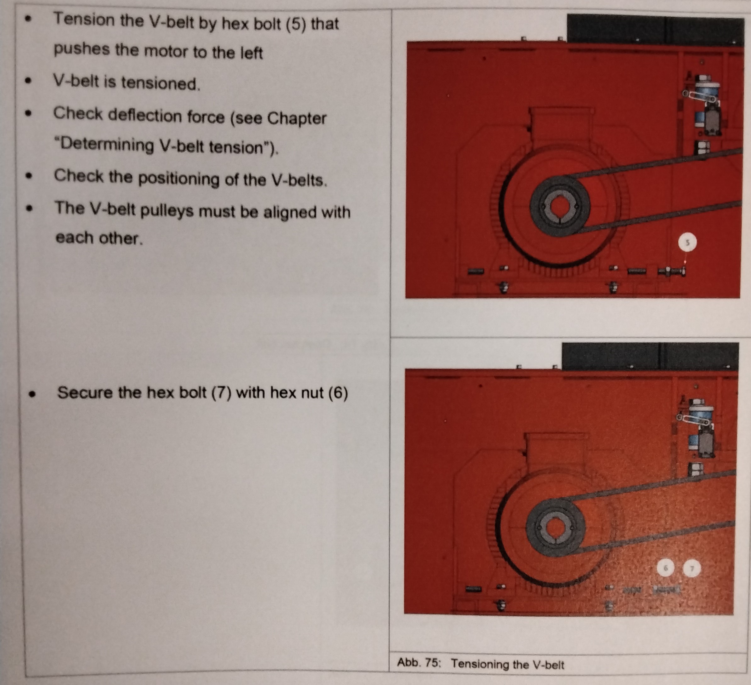
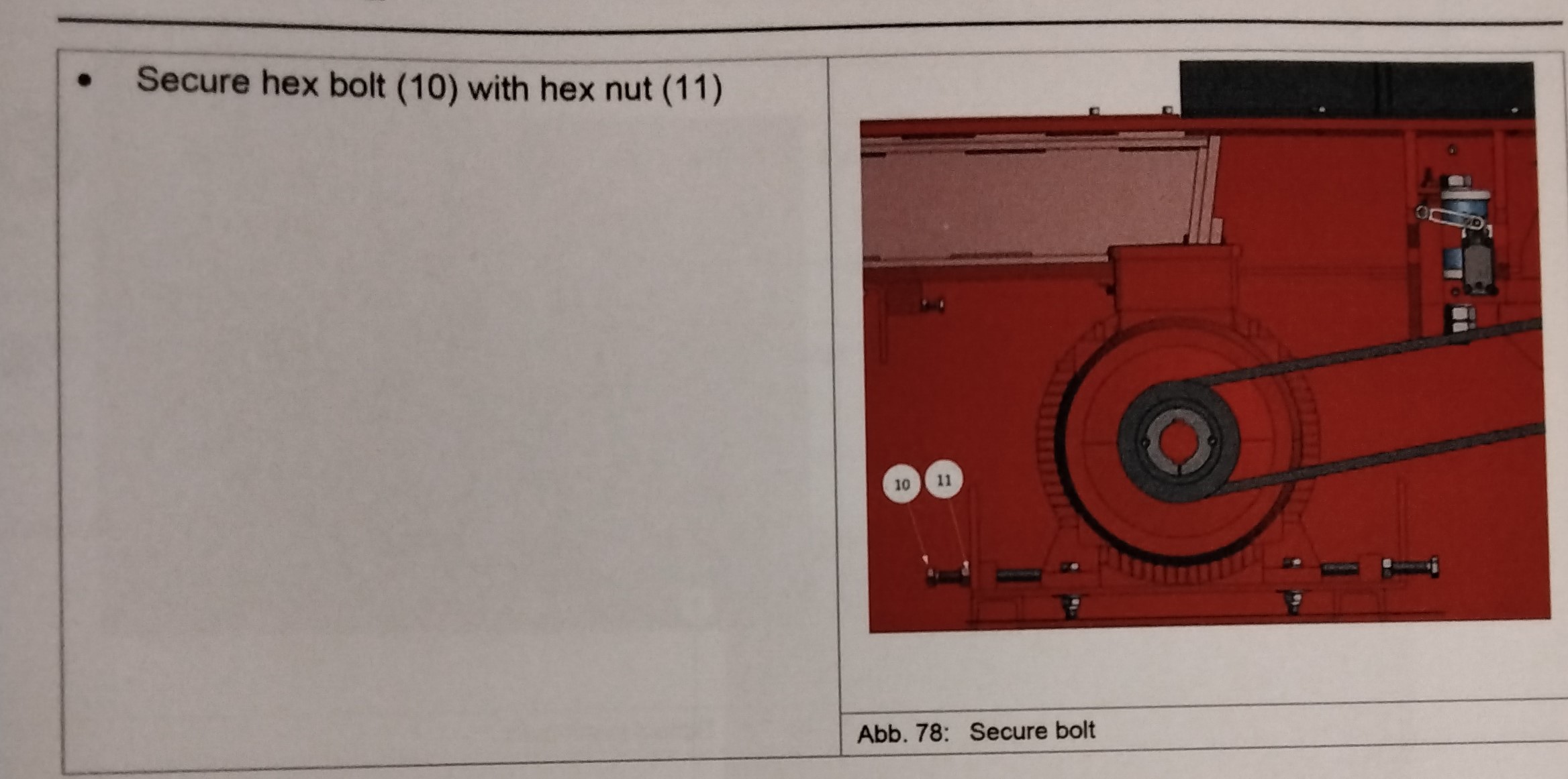
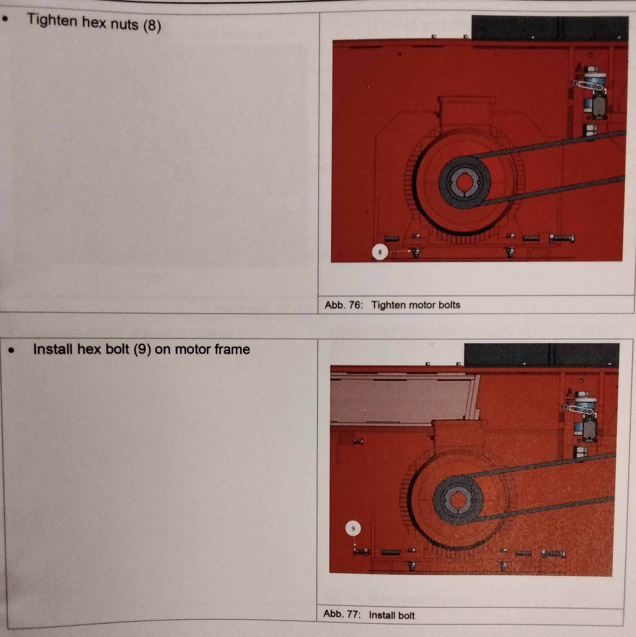
INCREASING V-BELT TENSION -Service may only be performed by trained personnel. -For safety instructions, see the operating instructions General part, Chapter "General Safety" -To adjust the belt tension, the belt cover has to be removed, see Chapter "Belt Cover"
DECREASING V-BELT TENSION -Servicing may only be performed by trained personnel. -For safety instructions, see the operating instructions General part "General Safety" -To adjust the belt tension, the belt cover has to be removed, see Chapter "Belt Cover"
MAINTENANCE 13
Follow the manufacturer's documentation General Maintenance Works: - Check the motor at regular intervals -Always keep the motor clean (Fan wheel, cooling fins, etc.) -Check the motor bearings (noises, measure vibrations, measure temperature, check for sufficient grease) and if necessary replace. LUBRICATION OF ELECTRIC MOTOR -Lubricate motors with grease nipples while they are running. -Only apply grease that is specified for the use on of ball bearings.
MAINTENANCE 14
CAUTION! Incorrect disposal of used oil! ---Environmental pollution. -Dispose of oil and dirty cloths so as not to pollute the environment. -Filter -Obey local environmental regulations The oil must comply with the cleanliness class of 18/16/13 according to ISO 4406 and NAS 1638. If oils are used that do not comply with the above mentioned quality requirements can possibly invalidate our guarantee obligation. We draw your attention particularly to the fact that each oil manufacturer or oil supplier is responsible for the quality of its product itself. VIDCOSITY OPERATING CONDITIONS CLASS ----------------------------------------------------------- 22 For very cold conditions or for extremely long lines. 32 For winter conditions 46 For summer conditions or closed rooms 68 For tropical conditions or for rooms with high temps 100 For excessively high temperatures NOTE: The code number of the viscosity classes (VG) refers to the midpoint viscosity in mm squared at T oil=40 degrees C NOTES REGARDING THE HYDRAULIC SYSTEM CAUTION! -Auxiliary components or equipment may only be connected to the hydraulic system and the already assembled components using the provided interfaces. Mechanical treatment (Drilling, milling, etc.)and thermal processing (welding, etc.) are not allowed. Especially the container for the compressed fluid may not be mechanically treated in no way. -There will be the risk of leakage and pollution. -Hoses may not contact hot components. -Pipe lines must be laid free from tension and sufficiently fixed with pipe clips. -Hose lines have to be secured against whipping in case people can be within the dangerous area. DEPRESSURIZING OF THE HYDRAULIC SYSTEM CAUTION! Possible dangerous situation! ---Risk of minor moderate injuries if not obeyed. CAUTION! Possible dangerous situation! ---There will be a risk of material damage if not obeyed. -Turn the machine off. -Secure the machine against accidental switching on. -Attach a safety sign "Do not switch on! Men working on equipment" on the switch cabinet. -The machine may only be depressurized by specialist personnel. -Disconnect the hose connections from the cylinders. -Collect the hydraulic oil in a suitable container. -The hydraulic system is now depressurized. GENERAL CHECKS: -Check the oil level in the oil reservoir and refill oil through the filler neck if necessary. -Check the oil temperature (recommended 50 degrees C, maximum 70 degrees C in continuous operation.) -check the clogging indicator of the installed filters and replace filters if necessary. -Check for unusual noise. -Check the fastening of the pipelines in case of varying pressure.
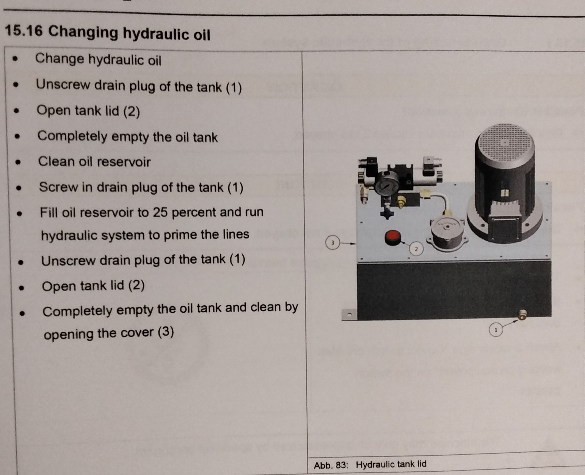
-Change hydraulic oil -Unscrew drain plug of the tank (1) -Open tank lid (2) -Completely empty the oil tank -Clean oil reservoir -Screw in drain plug of the tank. -Fill oil reservoir to 25 percent and run hydraulic system to prime the lines -Unscrew drain plug of the tank (1) - Open tank lid (2) -Completely empty the oil tank and clean by opening the cover (3) FILLING -Connect oil reservior with new oil pump unit. -Connect pump unit with hydraulic unit. -Start filling MANUAL FILLING -Insert filter into filler neck -Slowly fill in oil. FINISHING -During the first start-up filling, the oil will spread throughout the whole system. -the oil level will fall. -Replenish the oil.
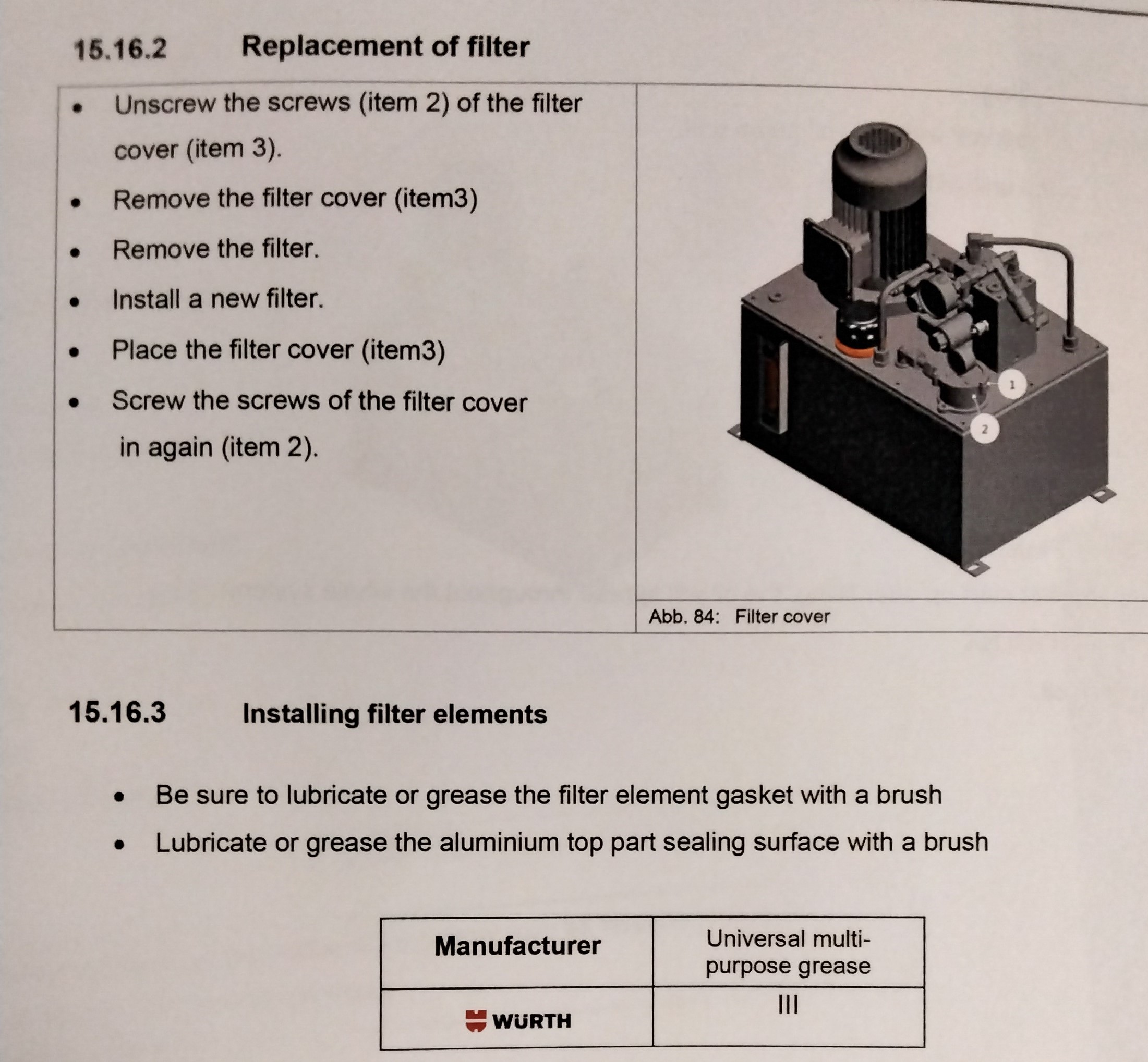
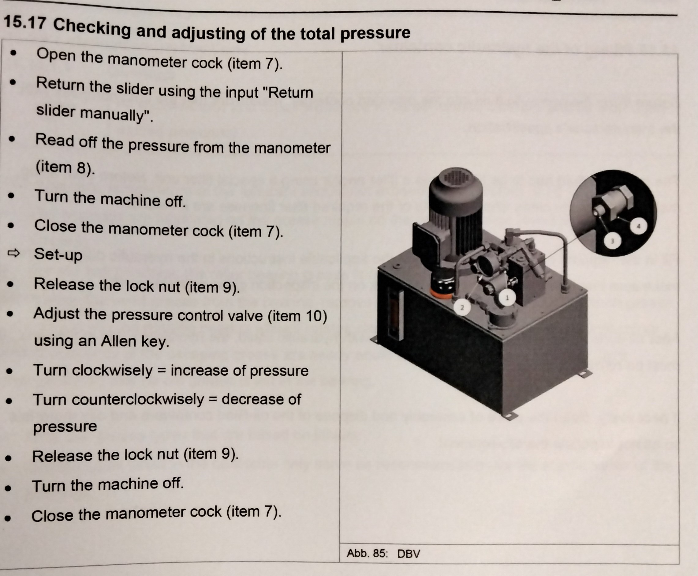
REPLACEMENT OF THE FILTER -Unscrew the screws (Item 2) of the filter cover (Item 3) -Remove the filter cover (Item 3) -Remove the filter -Install new filter -Place the filter cover (Item 3) -Screw the screws of the filter cover in again (Item2) INSTALLING FILTER ELEMENTS -Be sure to lubricate or grease the filter element gasket with a brush. -Lubricate or grease the aluminum top part sealing surface with a brush. -Use manufacturers preferred grease or equivalent grease with similar characteristics. -For hood filters, screw in the hood until it stops and then back off 10-15 degrees. CHECKING AND ADJUSTING OF THE TOTAL PRESSURE -Open the manometer cock (Item 7) -Return the slider using the input "Return slider manually" -Read off the pressure from the manometer (item 8) -Turn the machine off -Close the manometer cock (Item7) ---Set-up -Release the lock nut (Item 9) -Adjust the pressure control valve (Item 10) using an Allen key. -Turn clockwisely = increase of pressure -Turn counterclockwisely = decrease of pressure -Release the lock nut (Item 9) -Turn the machine off -Close the manometer cock (Item 7) The operating pressure preset at the factory may be changed only after consultation with the manufacturer.
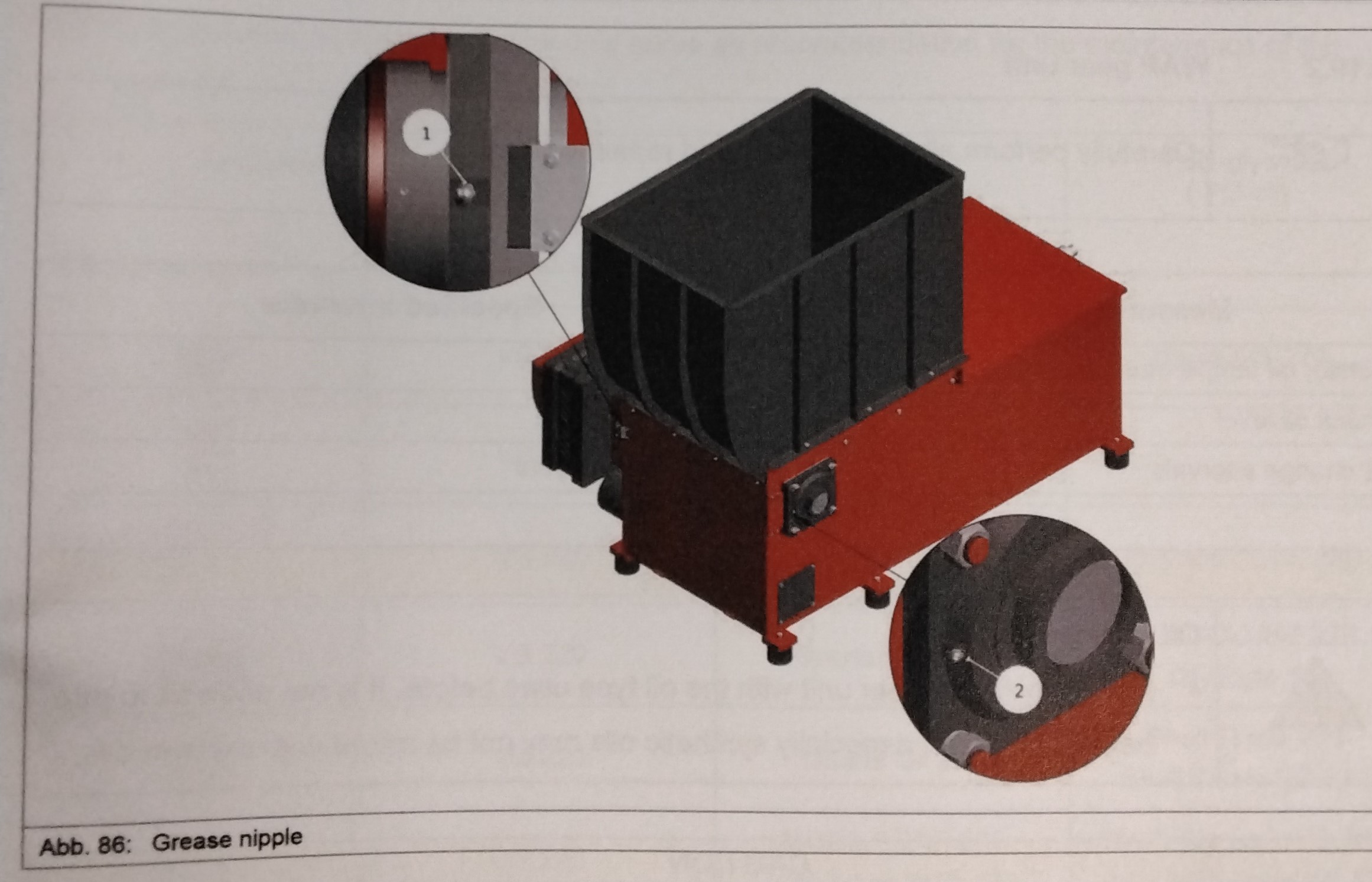
FILLING OF THE HYDRAULIC CONTAINER Before filling the hydraulic fluid into the provided container, make sure that the fluid complies with the manufacturers specification. The hydraulic fluid has to be filled in via a filter and/or using a special filter unit. Before start filling, make sure that the clean filter elements of the required filter fineness are installed. Fill in the required quantity complying with the applicable instructions in the hydraulic diagram and make sure that it does not exceed the fill mark on the inspection glass or dipstick. After all consumers and lines have been filled with hydraulic liquid in the tank must be refilled. Proceed as follows: If necessary, clean the place of assembly and dispose of the oil- filled containers and oily materials so as not to pollute the environment. LUBRICATION INSTRUCTIONS BEARINGS -All maintenance and repair works are to be performed carefully and by thoroughly trained personnel. The operating temperature of the lubricant should not exceed a temp of 70 degrees C. -The bearings are lubricated on the grease nipple on the bearing (see list of grease nipples). -For the ball bearings, the roller bearing grease is replaced. To remove the used grease from the bearing, remove the bearing plug and pump the fresh grease very slowly into the running bearing while it rotates slowly or runs with low idle speed until color and consistency of the escaping grease are nearly equal to the one of the new grease. This change shows that no old grease is left in the bearing. - Only use grease types that are based on lithium. -Grease types listed in the next table only serve as recommendation for the maintenance of the bearings.
MAINTENANCE 15
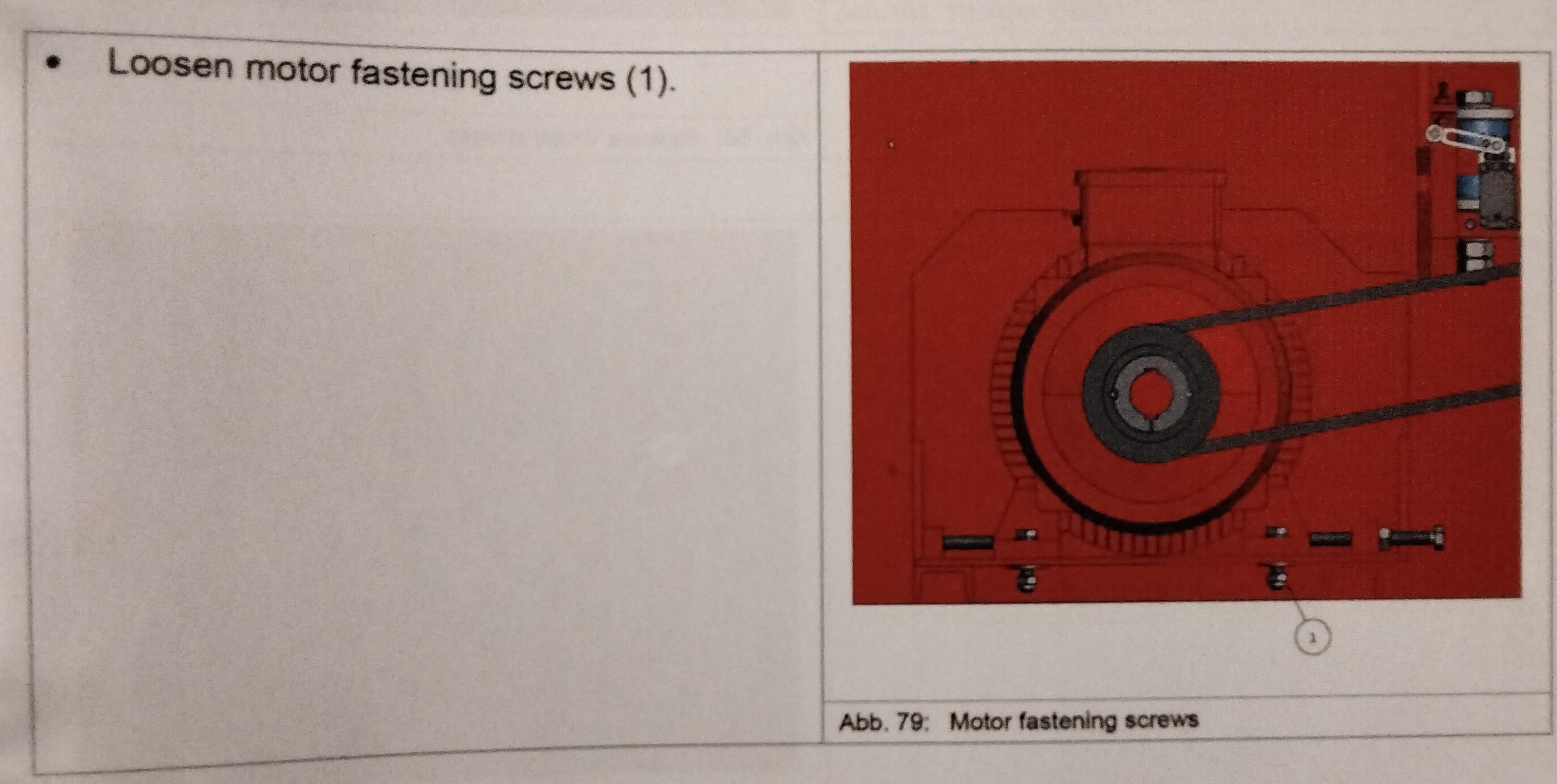
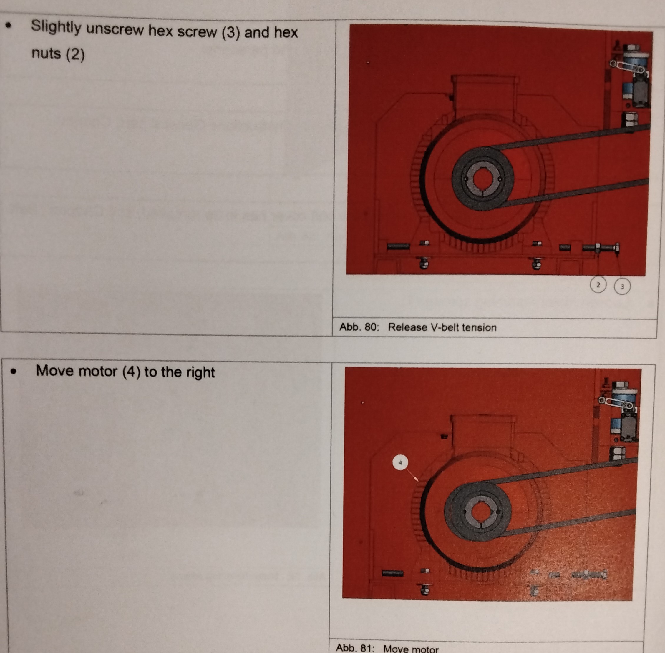
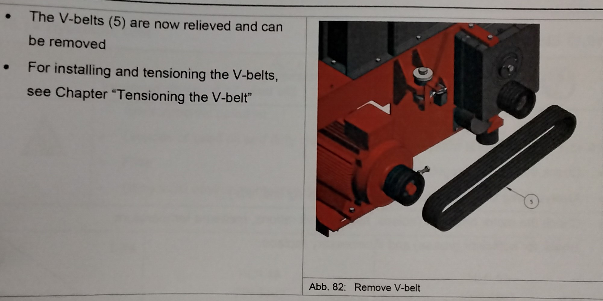
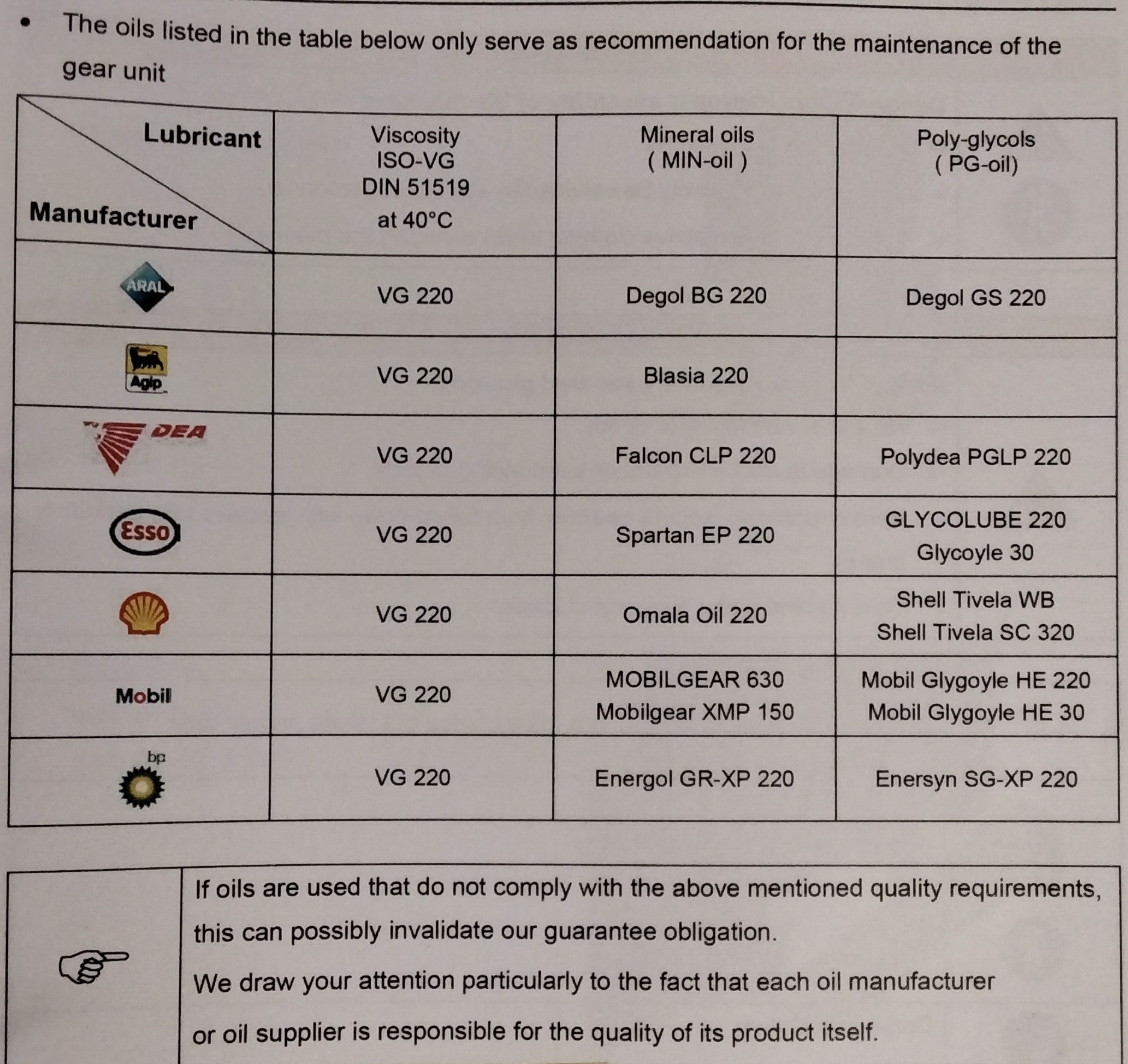
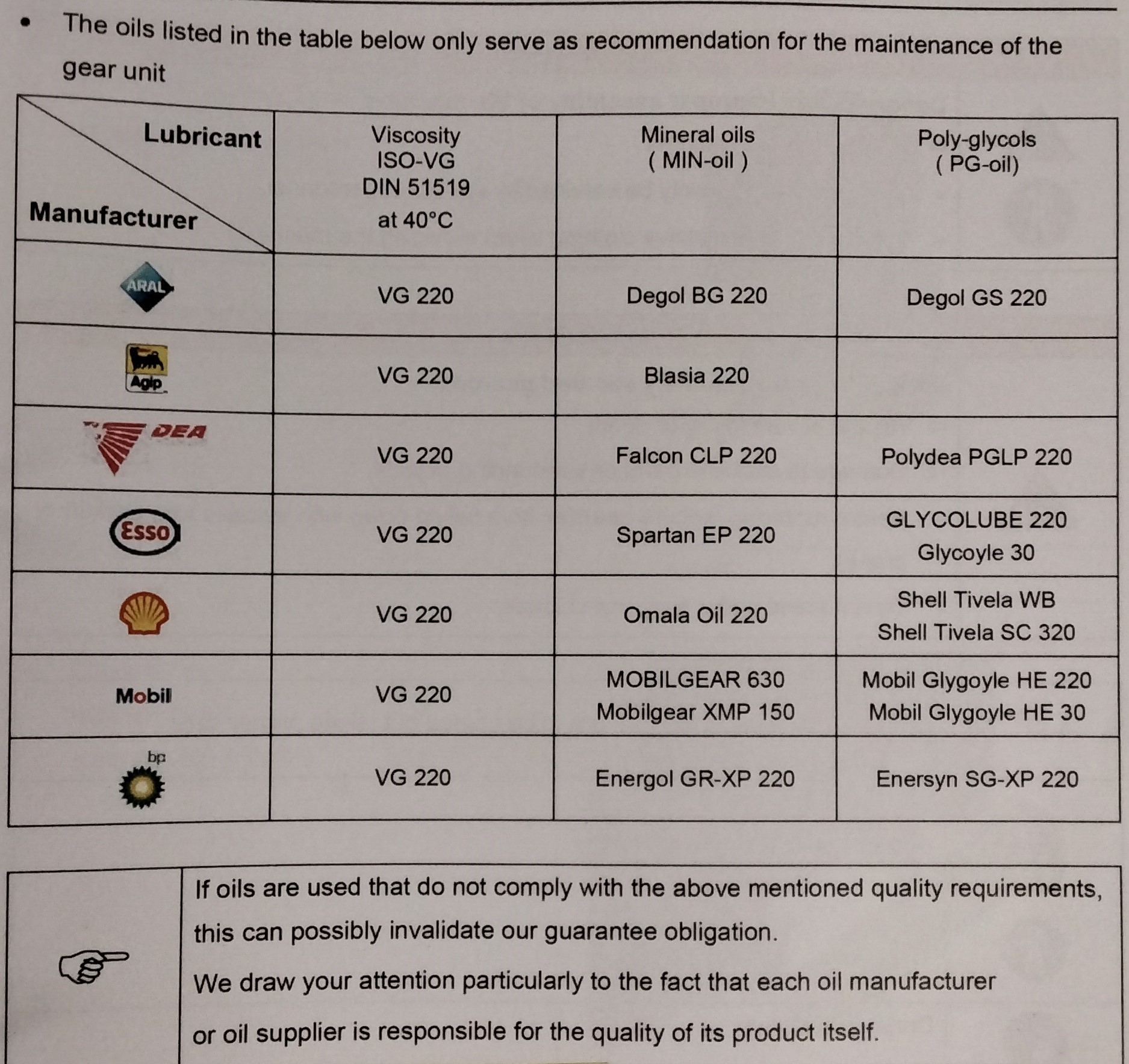
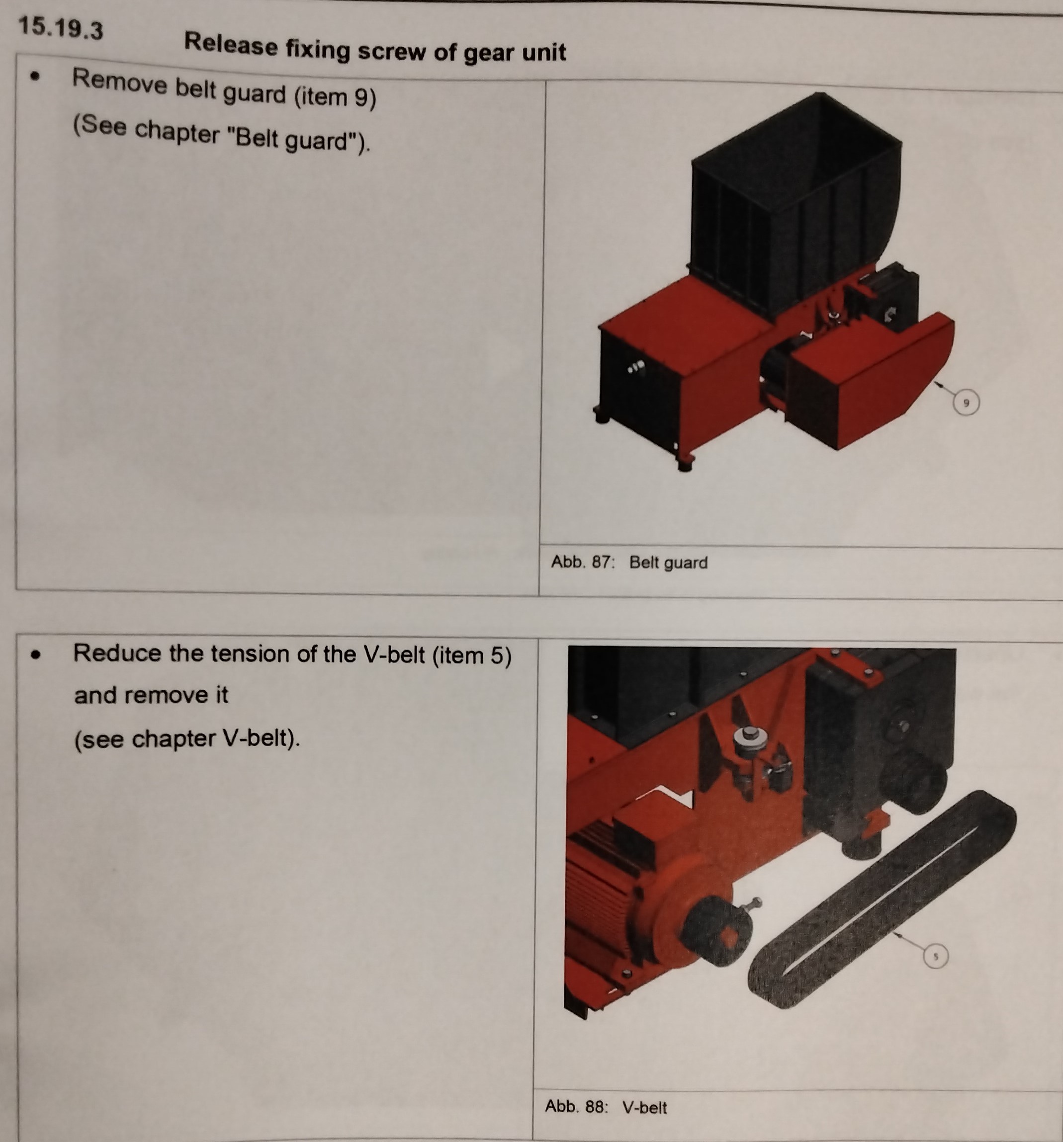
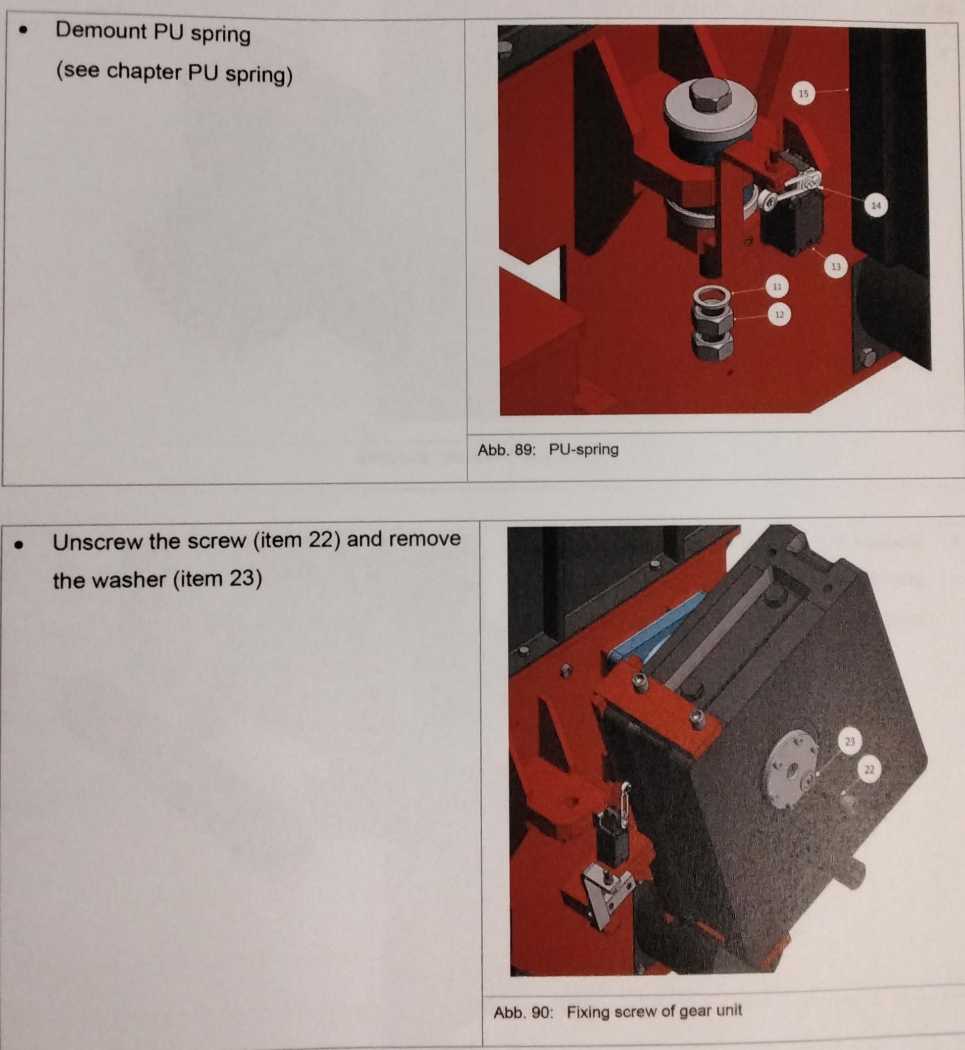
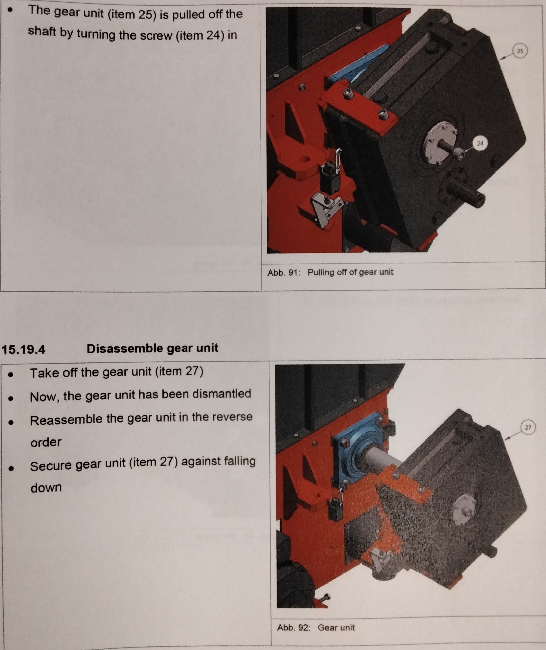
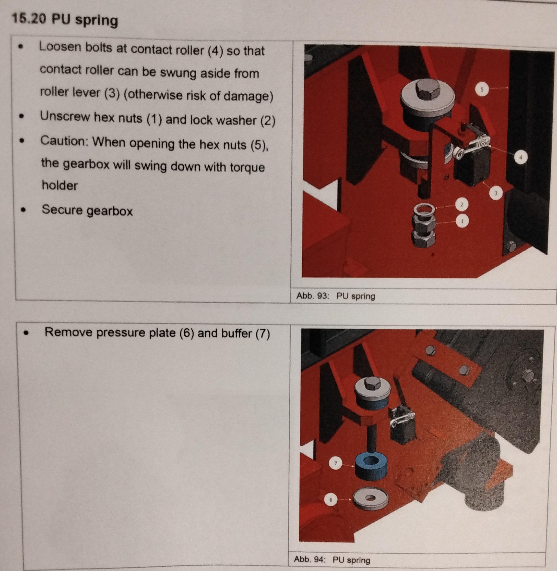
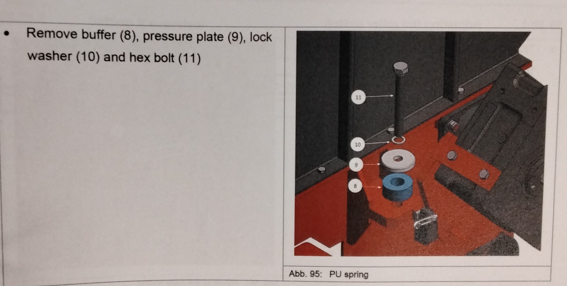
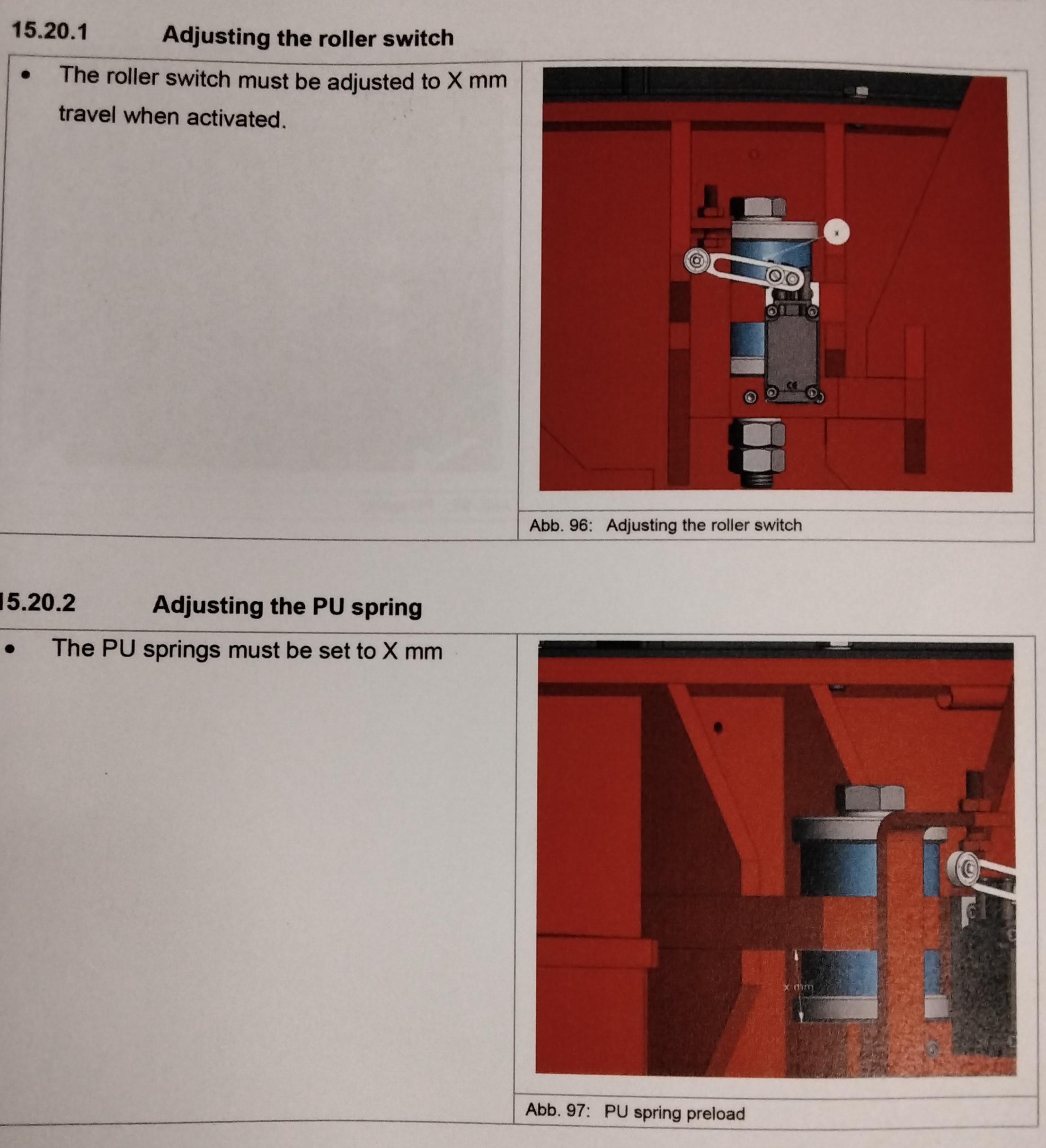
Carefully perform all maintenance and repair works. MEASURES TO SPECIFIED BE TAKEN INTERVALS ------------------------------------- Monitor oil temp Continuously and noise Check oil level Every 3 months Oil change intervals 2000 hours/year CAUTION! OIL CHANGE - Generally fill the gear unit with the oil type used before. It is not allowed to mix several types, especially synthetic oils may not be mixed with mineral oils. DRAINING THE OIL -The oil must be discharged immediately after the gear unit has been set out of service as long as the oil is still warm. -Allow the oil to drop off for a sufficiently long time to remove oil sludge, fines and oil residues. If lucent bronze fines are in the oil, this is fully harmless. The below listed oil quantities are planned for the use without oil cooler. If an oil cooler is used, the oil quantity increases depending on the length of the hose line. The oils listed in the table below only serve as recom- mendation for the maintenance of the gear unit. If oils are used that do not comply with the mentioned quality requirements, this can possibly invalidate our guarantee obligation. We draw your attention par- ticularly to the fact that each oil manufacturer or oil supplier is responsible for the quality of its product itself. WARNING! Danger to the machine. -The machine may only be serviced by specialist personnel. -Wear suitable protective clothing when servicing the machine. WARNING! Danger from inadequate secured gearbox - Risk of severe injury or death. -Damage to machine parts or surrounding objects. -Before replacing, secure gearbox from falling down with suitable tool (fork lift or crane) -Do not stand under suspended loads. Maintenance and repair work are to be carried out taking proper care. -Turn the machine off -Make sure that the machine can not be turned on accidentally. -Attach a safety sign "Do not switch on! Men working on equipment" on the switch cabinet. -Remove belt guard (Item 9) -Reduce tension of the V-belt (Item 5) and remove it. -Demount the PU Spring -Unscrew the screw (Item22) and remove the washer (Item 23) -The gear unit (Item 25) is pulled off the shaft by turning the screw (Item 24) -Take off the gear unit (Item 27) -Now, the gear unit has been dismantled -Reassemble the gear unit in the reverse order -Secure gear unit (Item27) against falling down. -Loosen bolts at contact roller (4) so that the contact roller can be swung aside from roller level (3) (otherwise risk of damage) -Unscrew hex nuts (1) and lock washer (2) -Caution: When operating the hex nuts (5), the gearbox will swing down with torque holder. -Secure gearbox -Remove pressure plate (6) and buffer (7) -Remove buffer (8), pressure plate (9), lock washer (10) and hex bolt (11)
MAINTENANCE 16
-The roller switch must be adjusted to X mm travel when activated. -The PU springs must be set to X mm SETTING X OVERVIEW MOTOR GEARBOX PU SPRING ROLLER SWITCH ------------------------------------------------------------- Dimension X/Y Dimension X (pre-tension) (pre-tension) WAP 60-80 7 mm
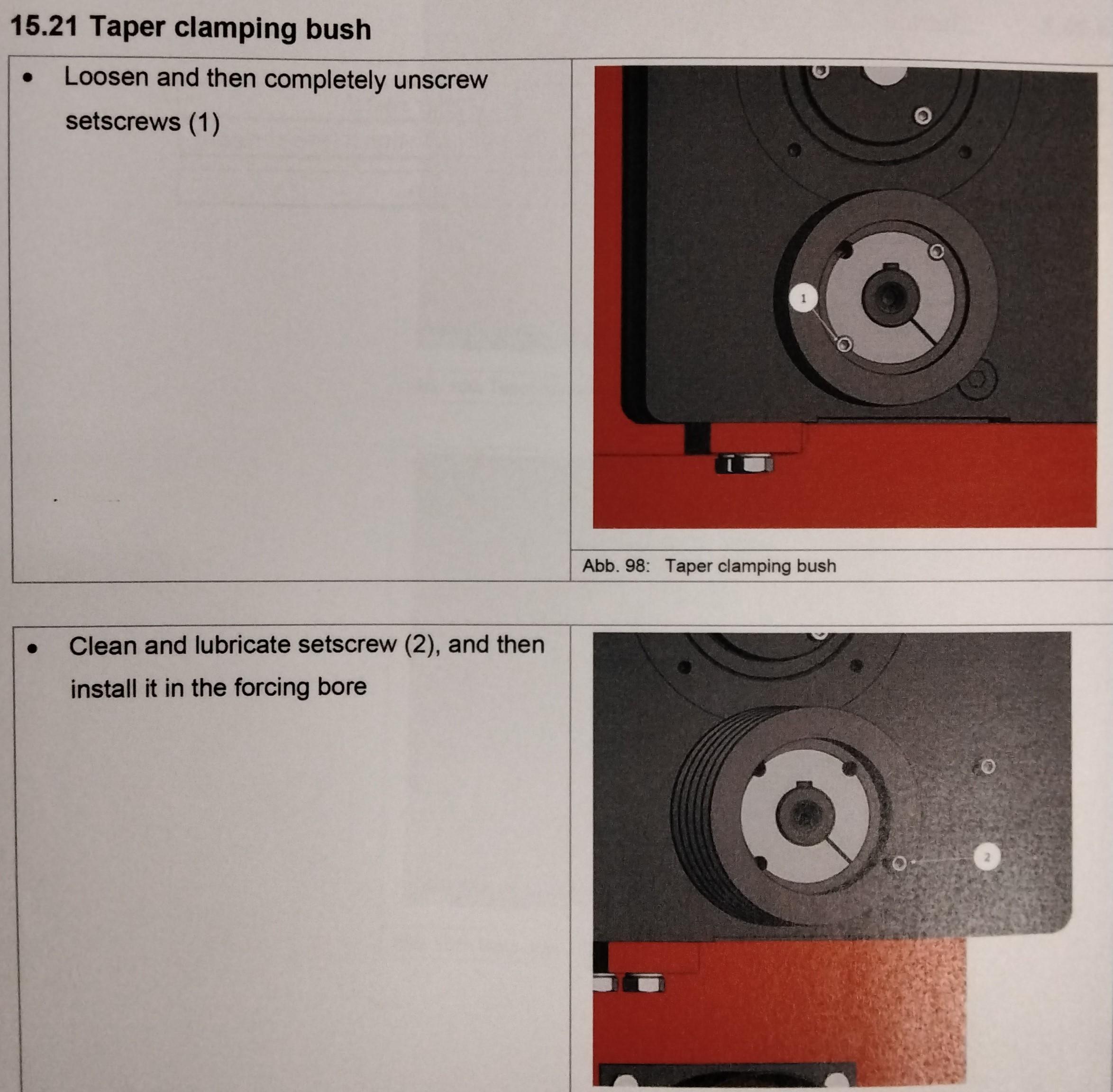
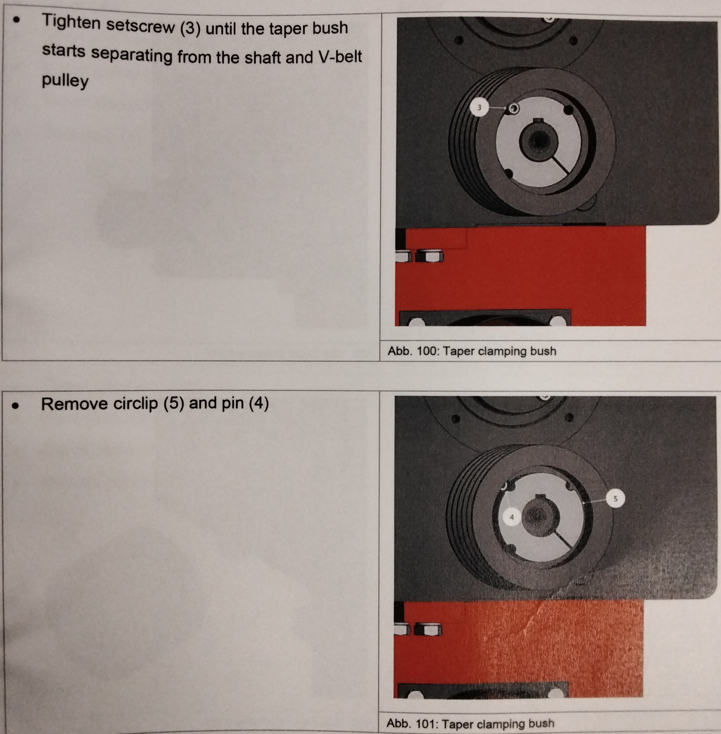
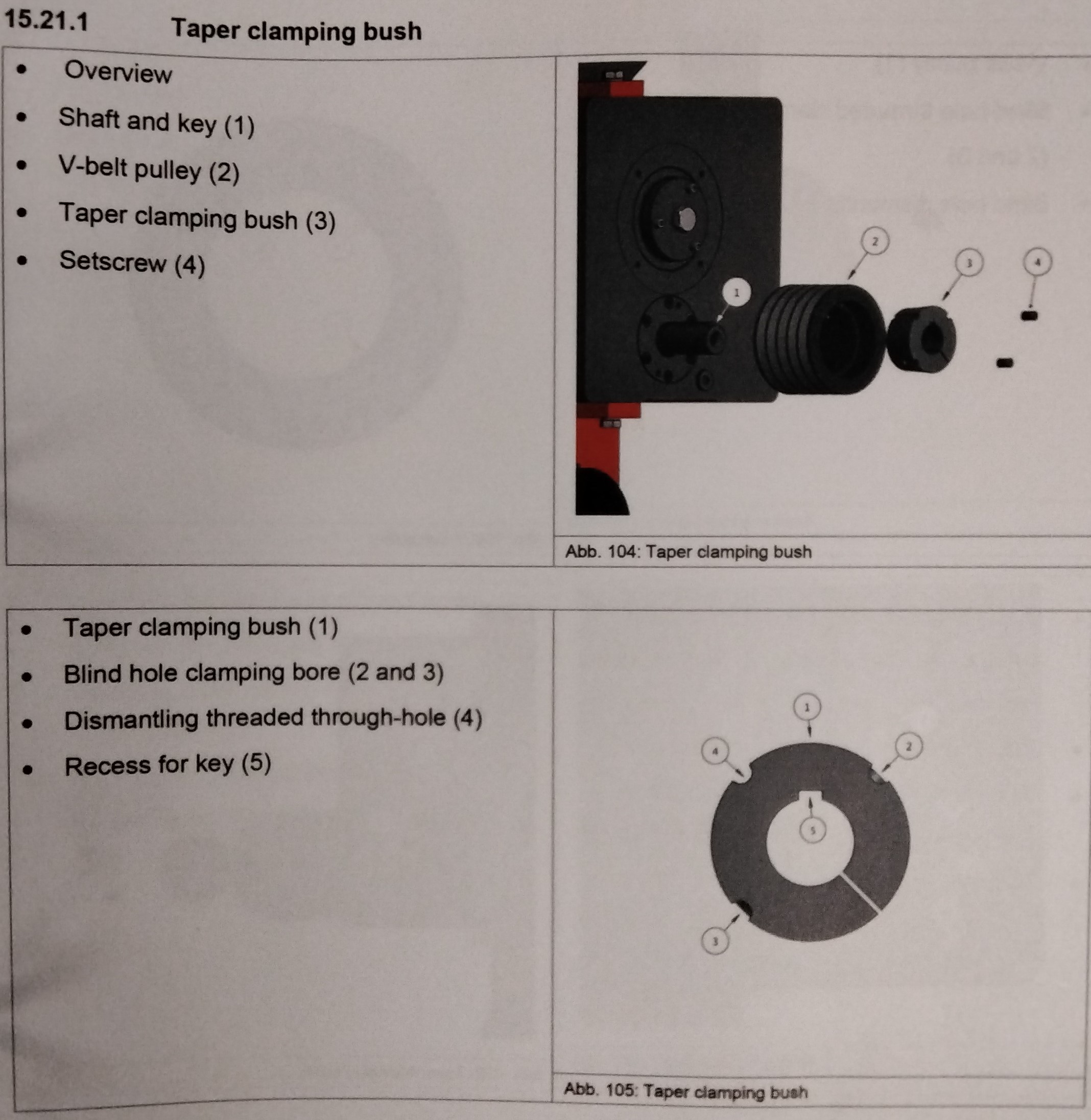
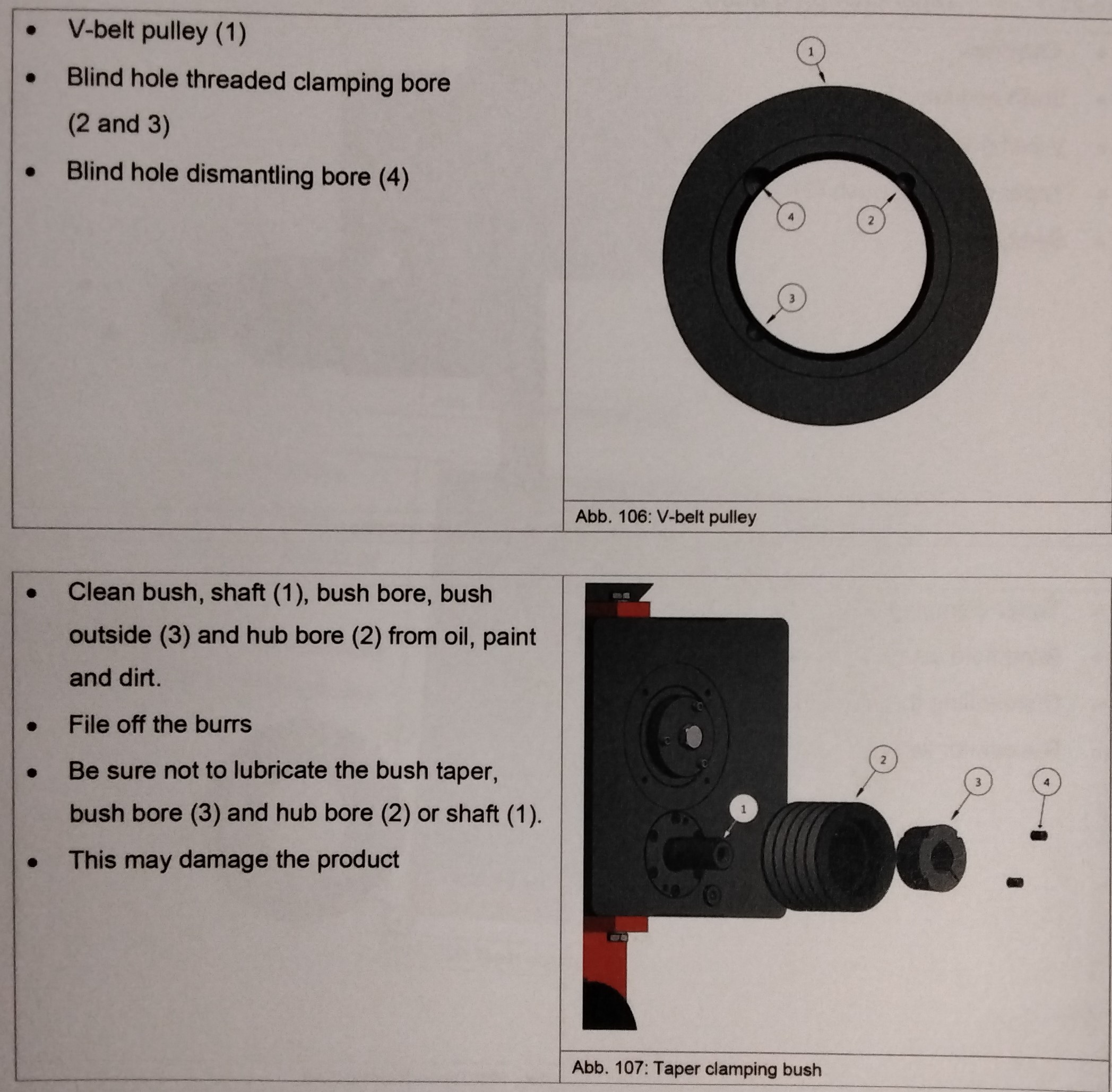
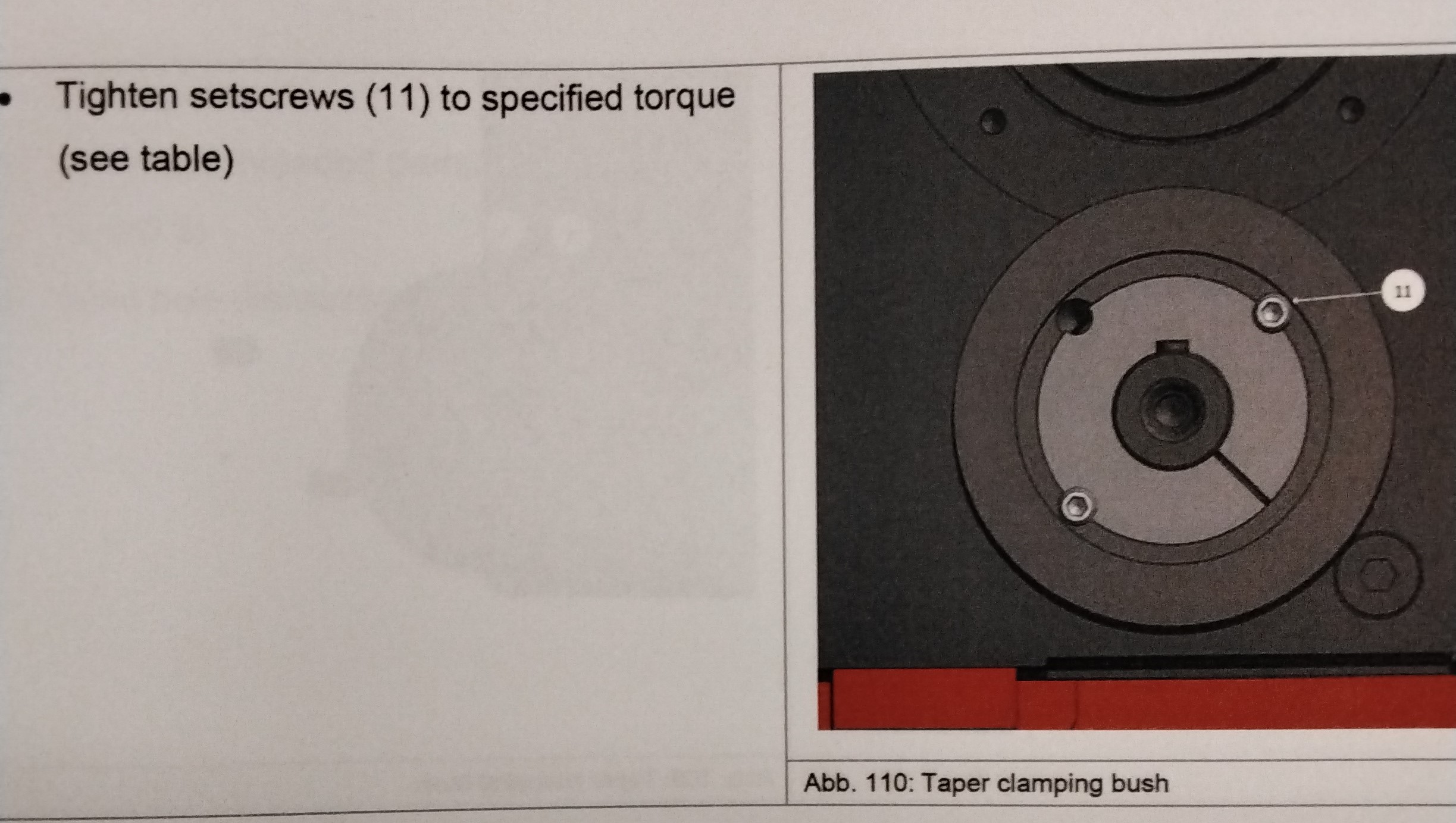
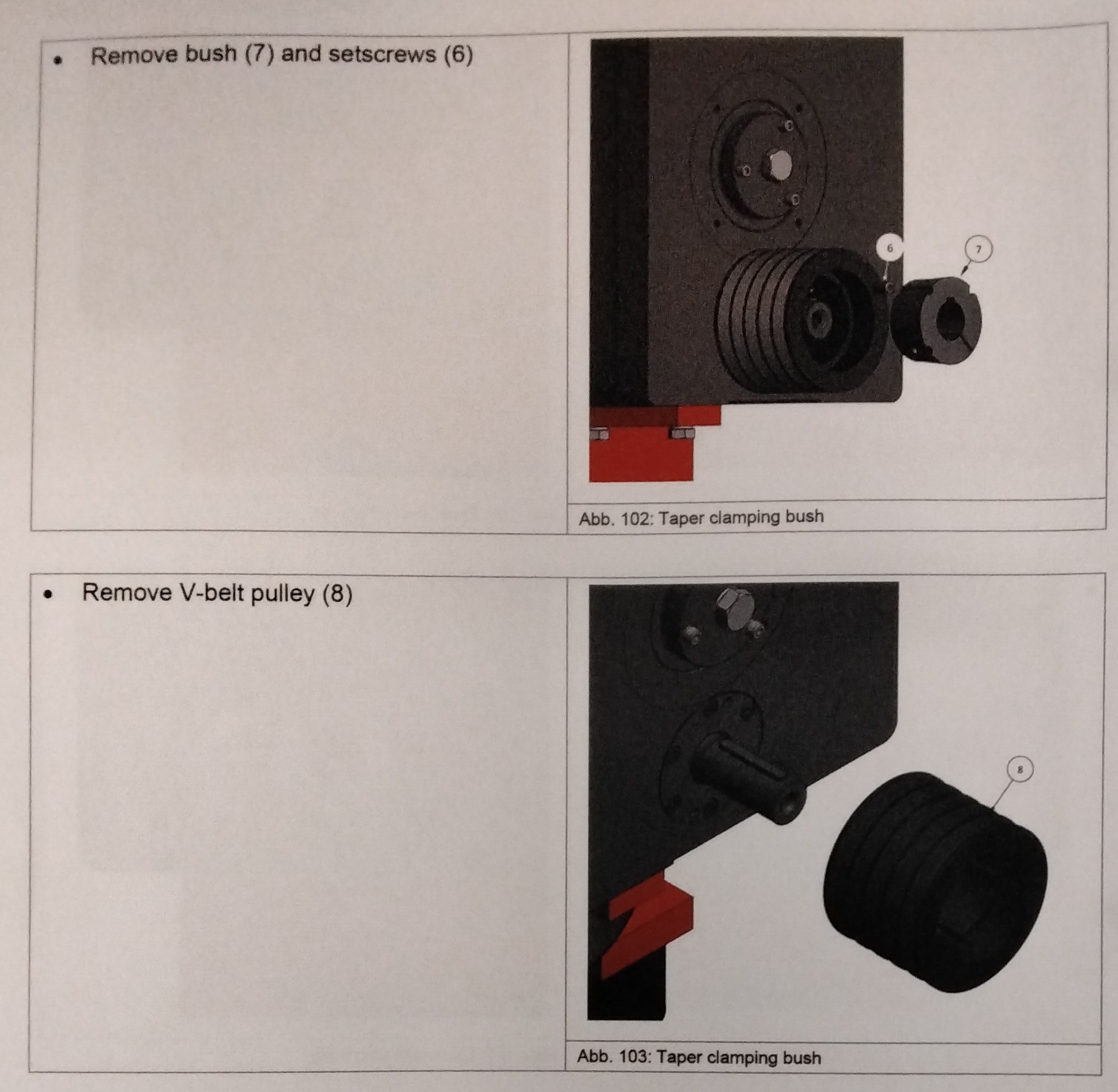
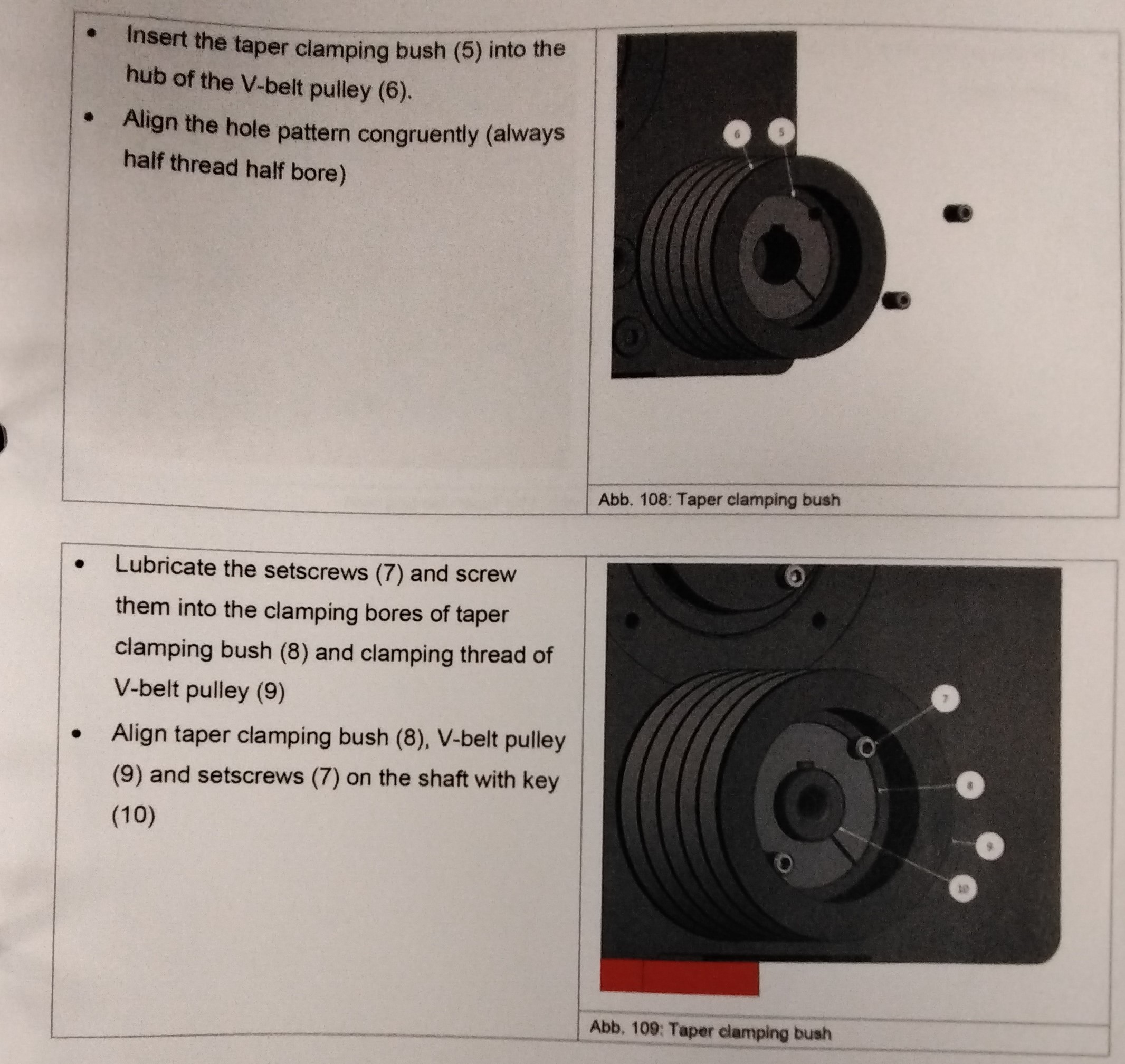
-Loosen and then completely unscrew setscrews (1) -Clean and lubricate setscrew (2), and then install it in the forcing bore. -Tighten setscrew (3) until taper bush start separating from the shaft and V-belt pulley. -Remove circlip (5) and pin (4) -Remove bush (7) and setscrews (6) -Remove V-belt pulley (8) -Clean bush, shaft (1), bush bore, bush outside (3) and hub bore (2) from oil, paint and dirt. -File off the burrs -Be sure not to lubricate the bush taper. -This may cause damage to the product. -Insert the taper clamping bush (5) into the hub of the V-belt pulley (6) -Align the hole pattern congruently (always half thread half bore) -Lubricate the setscrews (7) and screw them into the clamping bores of taper clamping bush (8) and clamping thread of V-belt pulley (9) -Align taper clamping bush (8), V-belt pulley (9) and set screws (7) on the shaft with key (10) -Tighten setscrews (11) to specified torque (see table)
Source: Ideal Cabinetry (Community Member)

