Nordson Series H-20 Automatic Applicators
Use this guide for the general maintenance and periodic maintenance of your automatic applicators to ensure that your equipment perform at its best for a long period of time.
Nordson Series H-20 Automatic Applicators
Use this guide for the general maintenance and periodic maintenance of your automatic applicators to ensure that your equipment perform at its best for a long period of time.
WARNING! Allow only personnel with appropriate training and experience to operate or service the equipment. The use of untrained or inexperienced personnel to operate or service this equipment can result in injury, including death, to themselves and others; and damage to the equipment. This section provides preventative maintenance procedures recommended for the H-20 applicator and attached hose. Maintenance instructions for the Melter can be found in the melter manual. WARNING! Failure to follow the following maintenance procedures may cause damage to the hose, improper system operation, or personal injury. GENERAL SYSTEM MAINTENANCE Follow the Procedures below: FREQUENCY PROCEDURE DAILY: - Inspect the applicator assembly. Any signs of adhesive in the bore hole in the side of the module indicates packing cartridge failure. Replace the module as described in Repair. - Clean all exterior surfaces of the applicator assembly. - Flush the H-20 applicator adhesive filter (if present) - Clean the hose exterior and inspect the hose hydraulic connections. - Keep the adhesive supply in the melter clean and free of contaminants. WEEKLY - Clean the H-20 applicator adhesive filter (if present). 6 MONTHS - With the power locked out, remove the electrical cover from the H-20 applicator and check that the heater and temperature sensor leads are tight and secure. Tighten any loose connections. Replace the heater and/or temperature sensor if any leads have bare wires that touch each other or the service block. NOTE: Vibration and heating/cooling cycles may loosen connections. This could result in damage to electrical components or improper operation of the system. - Flush the system, including the applicators. Refer to the melter manual for specific information. AS NEEDED - Clean the applicator nozzle. - Flush the system when changing over to a different adhesive.
MAINTENANCE
WARNING! Relieve system hydraulic pressure as described in the installation section before opening any hydraulic connection. FLUSH THE FILTER (IF PRESENT) Flush the filter daily or as dictated by plant operating conditions and adhesive type. 1. Bring the system to operating temperature. 2. Turn the melter pump off. 3. Place a drain pan below the H-20 applicator. WARNING! Risk of serious burns. Relieve hydraulic pressure before operating the drain valve. 4. Trigger all applicators to relieve system pressure. CAUTION! Risk of equipment damage. Use only a flat-blade screwdriver to open or close the drain valve. 5. Open the drain valve in the applicator service block with a flat-blade screwdriver by turning it counterclockwise. 6. Turn on the melter pump. 7. Slowly increase the pump speed until the draining adhesive is free of impurities, then turn off the pump. 8. Turn the applicator drain valve clockwise and close it. 9. Remove the drain pan and proceed with normal operation. CLEAN THE HOSE Keep the braid of the hose free of adhesive. Built up material can cause kinking when the hose is moved from one position to another. Clean any dust and debris from the work area. Inspect the Hose Hydraulic Connections 1. Relieve the system hydraulic pressure as described in Installation. 2. Inspect the hose fittings for tightness or cross threading. 3. If a hose fitting is loose, use two wrenches to tighten the hose swivel fitting onto the O-ring connector. Refer to Table 3 for the correct wrench size. 4. If a hose swivel fitting is cross-threaded onto its O-ring connector, undo the connection, then reinstall the hose swivel fitting properly. If adhesive leaks at a hose connection, refer to "Replace a Hose Connector O-ring" in Repair. 5. Resume normal operation.
CLEAN THE FILTER (IF PRESENT) 1. Perform steps 1 through 7 of the procedure "Flush the Filter" 2. Use a socket wrench or similar tool to unscrew then remove the filter from the service block. 3. Remove the screw from the filter bung. Then disassemble the filter. 4. Use any of the following three methods listed in Table 5 to clean the filter assembly: TABLE 5 Filter Component and Nozzle Cleaning Methods METHOD PROCEDURE A Place the filter components (except for the O-ring) and/or nozzle in a container of Nordson Type R fluid and heat the fluid until it is above the melting point of the adhesive. Scrub the filter components and/or nozzle with a fine bristled brush until clean. Wipe the components with a clean, dry cloth. WARNING! Risk of fire. Do not heat Nordson Type-R fluid above 246 Degrees C (475 degrees F). Use only a controlled heating device (such as a small deep fat fryer or thermostatically-controlled hot plate) to heat the fluid above the melting temperature of the hot melt material. NOTE: Do not use a metal brush. Damage may result preventing proper operation. B Use a flameless electric heat applicator or compressed hot air to heat the filter components and/or nozzle. Then wipe with a clean, dry cloth. C Use an ultrasonic cleaner filled with cleaning fluid to clean the filter components and/or nozzle. Then wipe with a clean, dry cloth. 5. Inspect the screen for damage. Any dents or breaks in the mesh means that the screen is damaged and should be replaced. Refer to "Parts" for the correct filter screen part number. Always use a filter with a smaller screen size than the orifice size. 6. Reassemble the filter components using a new O-ring. 7. Bring the system to operating temperature. CAUTION: Ensure that the applicator service block is at operating temperature when the filter is reinstalled. Cold material on the filter or service block walls can cause the filter screen to collapse. 8. Thread the filter into the service block until hand tight. 9. Ensure that the applicator drain valve is open and a drain pan is below the drain valve. Turn on the melter pump and pump adhesive until is clean and free of all contaminants. 10. turn off the melter pump. 11. Use a flat-blade screwdriver to close the applicator drain valve. 12. Tighten the filter until it seats. DO NOT OVER TIGHTEN. 13. Remove the retaining nut and nozzle and turn on the melter pump. Trigger the applicator and allow adhesive to flow through the applicator and into the drain pan until the flow is free of impurities. 14. Turn off the melter pump and reinstall the applicator nozzle and retaining nut. 15. Remove the drain pan and resume normal operation.
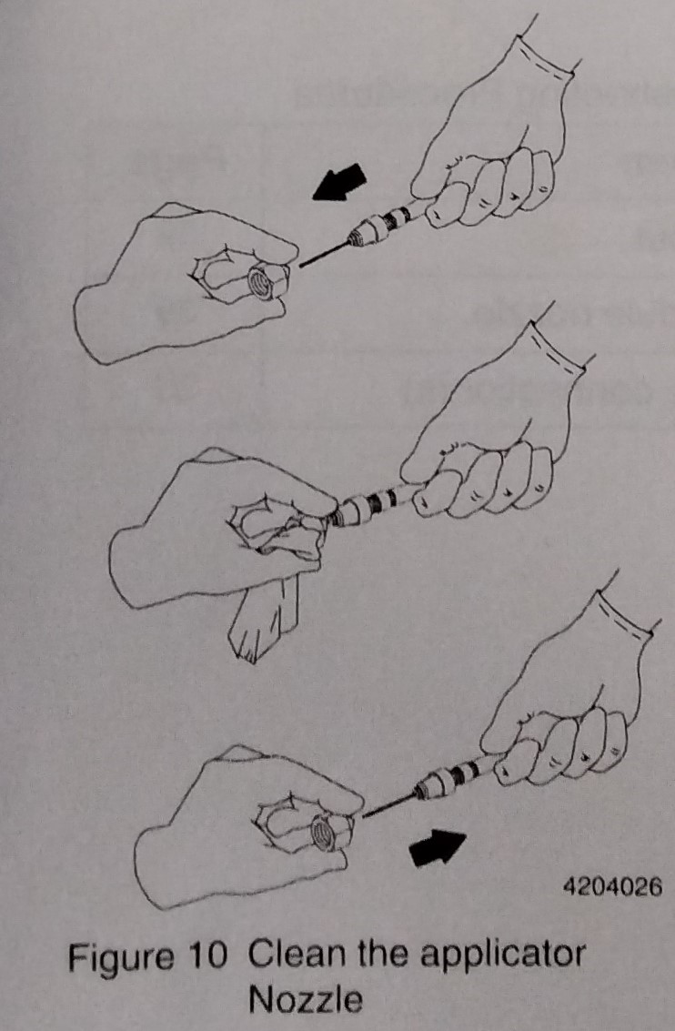
Nozzle clogging occurs when a filter screen is damaged or when there is charred material in the hose or applicator. Char may form if adhesive is heated above the application temperature recommended by the adhesive manufacturer. If nozzle clogging or char formation occur, it may be necessary to replace the module. CLEAN THE NOZZLE If nozzle clogging persists, remove the applicator assembly from its installation, remove the module, and totally clean the service block hydraulic passage. Clean all nozzles each week or as needed. See Parts for the nozzle cleaning kit part number. To replace an existing nozzle with a nozzle of a different orifice size on an H-20 filtered applicator, refer to the Table of "Optional Filter Screens in Parts". Always use a filter with a smaller screen size than the nozzle orifice size. Use this procedure to clean the applicator nozzle: 1. Relieve hydraulic pressure as described in "Installation". WARNING! HOT! Risk of burns. Wear safety gloves. Failure to observe may result in personal injury. 2. With a drain pan beneath the applicator module. use a 21 mm (13/16 in.) wrench to loosen and remove the nozzle retaining nut and nozzle. 3. Use any three methods in Table 5 to clean the applicator nozzle. 4. See Figure 10. Use a probe to clean the nozzle bore. Nordson nozzle cleaning kits include the holder and a variety of probes. 5. Reinstall the nozzle and retaining nut onto the applicator. 6. Remove the drain pan and restore the system to normal operation.
TROUBLESHOOTING
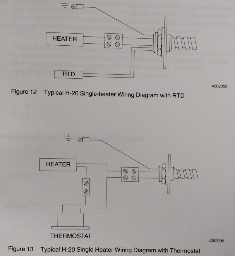
WARNING! Allow only personnel with appropriate training and experience to operate or service the equipment. the use of untrained or inexperienced personnel to operate or service the equipment can result in injury, including death, to themselves and others, and damage to the equipment. This section includes fault isolation and correction procedures for problems that can occur during operation of the series H-20 applicator. During the daily visual inspection, correct obvious causes of malfunction, such as broken or missing electrical pins or wires or damaged hose plugs. Note that a problem may have more than one possible cause. Therefore, refer to all charts before beginning to correct a problem. H-20 applicator wiring diagrams are located at the end of this section for reference when disconnecting and reconnecting heater, thermostat, and cordset leads.
TROUBLESHOOTING ELECTRICAL
ELECTRICAL PROBLEM POSSIBLE CAUSES CORRECTIVE ACTION 1. No or little adhesive output No power to the melter Ensure that input power to the melter is connected and the main disconnect switch is ON Applicator does not Refer to "Applicator heat or heats only does not heat or slightly heats only slightly" Temperature settings of RESET one or more channels are too low for the adhesive Electrical fault with melter Inspect the melter pump pump. Refer to the appropriate manual Faulty hose heater (hose is Inspect the hose. cold or only slightly warm) Refer to appropriate manual. Triggering device not Troubleshoot Triggering working or not set correctly Device. Electrical fault with solenoid Verify faulty solenoid: valve 1. Bring the applicator to application temperature. 2. Ensure that power to the solenoid is on. 3. Manually trigger the solenoid. 4. If the applicator works, replace the solenoid. 5. If the applicator still fails, rebuild or replace the applicator. 2. Applicator does not No power to melter Ensure that input power to the heat or heats only slightly melter is connected and the main
PROBLEM POSSIBLE CAUSES CORRECTIVE ACTION No power to applicator heaters Inspect the melter pump. Refer to the at melter hose cordset socket. appropriate manual. Failed hose cordset Use the Nordson Hose/Applicator Diagnostic Device (refer to "Mics. Spare Parts and Service Kits" in the "Parts" section for the part number)to verify failed hose cordset. If this is not available, use the following procedure: 1. Switch off the melter and disconnect input power. 2. Unplug the hose cordset from the melter 3. Unplug the applicator cordset from the hose. 4. Locate the applicator heater pin pairs in the hose cordset plug and the socket at the other end of the hose. Check each pair for continuity. 5. Locate the applicator temperature sensor pin pairs in the hose cordset plug and the socket at the other end of the hose. Check each pair for continuity. 6. Replace the hose if any pin pairs indicate no continuity.
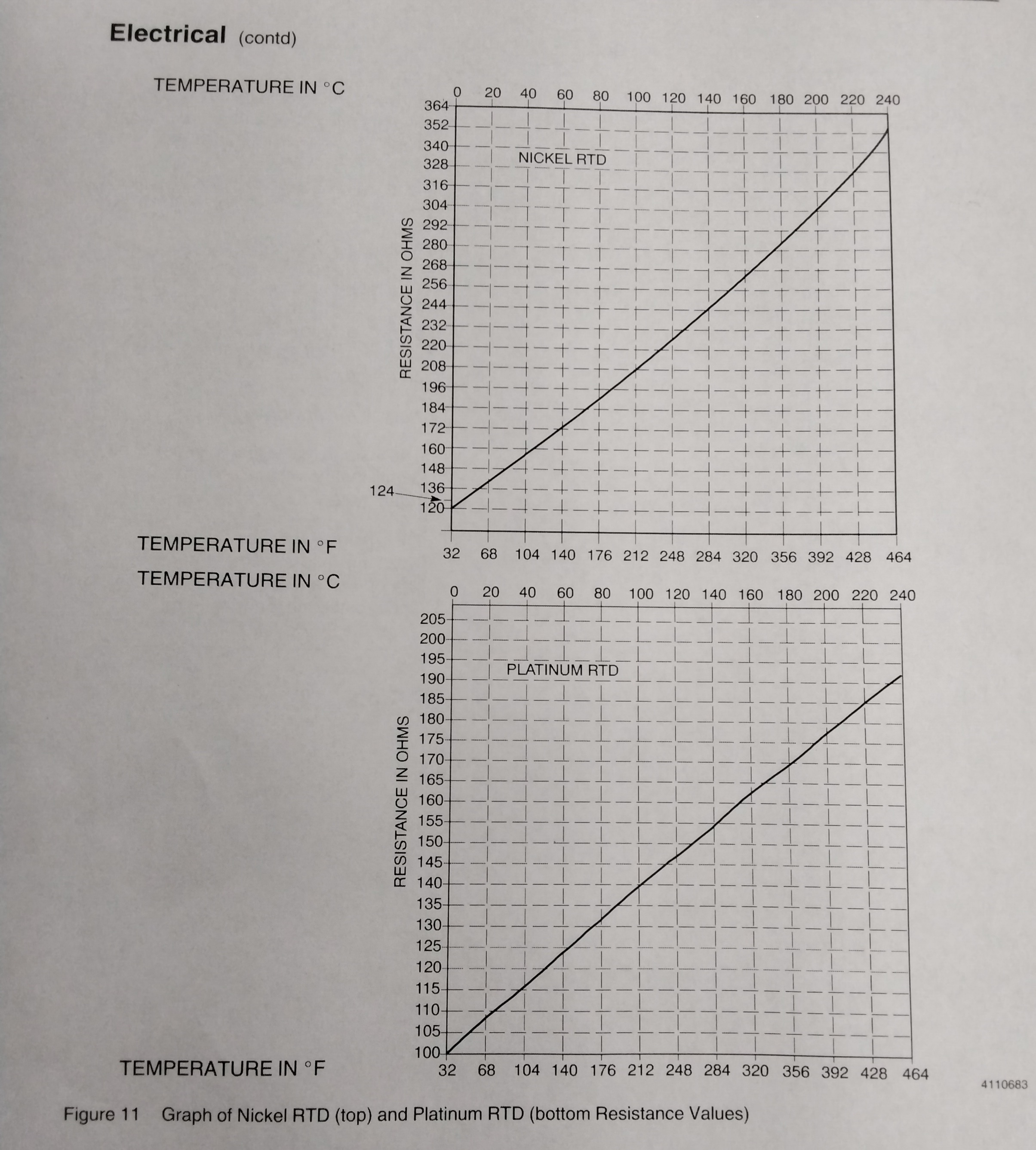
PROBLEM POSSIBLE CAUSES CORRECTIVE ACTION Applicator does not Failed applicator Use the Nordson Hose/Applicator heat or heats only slightly cordset Diagnostic device (refer to "Misc. Spare Parts and Service kits" in the "Parts" section for the part number) to verify failed applicator cordset. If this is not available, use the following procedure: 1. With the applicator cordset unplugged from the hose socket, remove the screws that secure the electrical cover to the applicator service block then slide back the cover . to expose the wiring connections 2. Disconnect the cordset leads from the heater leads and thermostat (if present) 3. Locate the heater pin pairs at each end of the applicator cordset and check each pair for continuity. No continuity indicates a failed cordset. 4. (RTD applicators) Locate the applicator RTD pin pair in applicator cordset plug. Check each pin pair correct resistence value using a multimeter.
Applicator does not heat or Failed Heater(s) With the heater the leads disconnected from heats only slightly the cordset (and thermostat, if present) check each pair of heater leads for continuity. No continuity indicates a faulty heater. Replace faulty heater(s) as described in the "Repair" section. Failed Thermostat Verify failed thermostat: 1. Touch one probe of the voltage tester to a heater/thermostat connection and other probe of the voltage tester to the power lead/thermostat connection. 2. Apply input power. 3. The voltage tester reading should be (0) until the thermostat opens at its rated temperature. 4. If the thermostat opens before reaching its rated temperature, disconnect and lock out input power and replace the thermostat as described in "Repair."
HYDRAULIC
PROBLEM POSSIBLE CAUSE CORRECTIVE ACTION 1. No or little adhesive Clogged nozzle Clean. Refer to "Maintenance". output. Filter screen blocked (if present) Contamination at the ball Remove the seat from the module, and seat (or needle and seat then clean the ball (or needle) tip and seat. in micro-adjust modules.) If problem persists , replace the module. 2. Adhesive leaks from Faulty module ball and Remove the seat from the module, then clean module nozzle seat assembly. the ball (or needle) tip and seat. If problem continues, replace the module. 3. Adhesive leaking at Loose or cross-threaded Undo, then redo hose connection as described in hose connection(s) connection "Maintenance" under "Inspecting the Hose Hydraulic Connections". Faulty hose connector O-ring Replace. Refer to "Repair".
PNEUMATIC
PROBLEM POSSIBLE CAUSE CORRECTIVE ACTION 1. No or little adhesive output Module not completely Ensure that input air pressure to the solenoid is opening 276-483 kPa (40-70 psi). Failed module air piston Rebuild or replace. assembly 2. Adhesive leaks from module Module air piston not Ensure that air supply to module is fully off nozzle closing when the solenoid is not triggering.
ADHESIVE APPLICATION
PROBLEM POSSIBLE CAUSE CORRECTIVE ACTION 1. Adhesive spitting on Adhesive in melter tank or If material level is cold, raise tank or reservoir extrusion reservoir is cold, low or depleted setpoint: if material level is low, refill. and pump is drawing in air. Hydraulic pressure set below Increase hydraulic pressure. Refer to melter manual. recommended minimum Adhesive output exceeds maximum Reduce output. Refer to melter manual. continuous delivery rate of system 2. Waves in bead deposit Set point too low Increase Ambient temperature too low in work Ensure ambient temp in work area is 0 degrees C area to 50 degrees C (32 F to 120 F) Applicator and nozzle subject to draft Prevent draft or breeze at applicator and nozzle. and breeze. Nozzle too far from substrate Reposition nozzle closer to substrate. Recommended nozzle to substrate distance is 13 mm (0.50 in.) 3. Excessive adhesive at Hydraulic pressure too high Reduce pressure beginning of bead. Excessive material delivery Nozzle too large. Replace. Refer to "Maintenance". Partially clogged nozzle Clean or replace. Refer to "Maintenance". Insufficient air pressure to Increase applicator 4. Excessive adhesive at end of bead Hydraulic pressure too low. Increase Adhesive too cold Raise applicator, hose, and melter setpoint temps. Insufficient air pressure to applicator Increase 5. Adhesive stringing at Nozzle too far from substrate Reposition nozzle. Recommended nozzle to substrate cut off Distance is 13mm (0.50 in.) Adhesive too viscous Increase temp or change to compatible adhesive with lower viscosity Adhesive too cold Raise applicator, hose, and melter setpoint temps. as required. Applicator speed too slow Use an air-piloted relay valve between solenoid and applicator, or reduce distance between
PROBLEM POSSIBLE CAUSE CORRECTIVE ACTION 6. Adhesive drooling from Module spring force too low Adjust applicator (micro-adjust H-20 modules only) Ball or needle and seat of Clean or replace, Refer to "Repair". applicator module worn or partially clogged by char 7. Adhesive bouncing or Adhesive too hot Decrease applicator, hose, and melter setpoint splashing from substrate temps. as required. Hydraulic pressure too high Decrease Adhesive viscosity to low Decrease temp or change to compatible adhesive with higher viscosity. Nozzle diameter too small Change to larger diameter nozzle, as described in the "Maintenance" section. 8. Adhesive fuming or smoking Temp setpoints to high Lower system setpoints Use of unstable adhesive Flush system and refill with different adhesive 9. Adhesive charring in system Temp setpoints too high Lower setpoints overheating in applicator, Locate and repair overheating component. hose or melter component Adhesive level kept too low Keep adhesive level higher in the melter. Adhesive oxidizing in melter Keep melter tank lid closed during operation. If tank problem persists, change to different adhesive or switch to a melter equipped with nitrogen blanket Adhesive kept at application temp Reduce applicator, hose, and melter temps slightly during long period of low activity during prolong hold situations 10. Adhesive gels System not flushed before Attempt to pump remaining adhesive from changing to new adhesive system, then properly flush the system and refill with fresh adhesive. . Type R-fluid used to flush Attempt to pump remaining adhesive from system, system previously used with then properly flush the system with compatible Polyamide, Surlyn, Polyester, or flushing agent (consult with adhesive manufactur
if the answer is " "
PROBLEM POSSIBLE CAUSE CORRECTIVE ACTION 10. Adhesive gels Adhesive heated for too Do not heat adhesive longer than recommended pot long life of adhesive: reduce applicator, hose, and melter temps slightly during prolonged hold situations. Adhesive heated at too Reduce temperature or consult with adhesive high a temperature manufacturer about recommended temperature range. 11. Adhesive not penetrating Adhesive not hot enough Increase channel setpoints substrate Special coating on substrate Increase system setpoints. If condition persists, check with adhesive manufacturer for compatible adhesive. Not enough adhesive use higher flow-rated nozzle, increase system being applied temperatures slightly, or increase hydraulic pressure at the melter pump Adhesive too viscous or gelled Increase temp or change to compatible adhesive with lower viscosity. 12. Unequal deposits Different nozzle sizes used on Use same size nozzles between nozzles in multi several modules module installations unequal spring force (micro- adjust H-20 modules only) Adjust module spring force. Nozzle clogged or damaged Clean or replace applicator nozzle as described in the Maintenance Section. Foreign material in applicator Rebuild or replace module. Refer to repair module Unequal hydraulic pressure at Compensate by using different nozzle sizes or applicators adjusting applicator travel. Adhesive in air piston section Rebuild or replace module. Refer to "Repair". of module
PROBLEM POSSIBLE CAUSE CORRECTIVE ACTION 13. Container pops open Adhesive not cooling fast 1. Decrease bead size. after leaving compression enough 2. Decrease adhesive temperature section 3. Increase nozzle-to-substrate distance 4. Increase distance between bead deposit and bead compression 5. Increase length of compression section. 6. Reduce line speed through compression section. 7. Cool the substrate 8. Use lower flow-rated nozzle, or use stitched bead pattern. Adhesive open time too long Use an adhesive with shorter open time or reduce application temperature. Adhesive cooling too fast 1. Increase bead size. 2. Increase adhesive temperature 3. Decrease nozzle-to-substrate distance 4. Decrease distance between bead deposit and bead compression. 5. Decrease length of compression section. 6. Raise line speed through compression section. 7. Heat the substrate 8.Use higher flow-rated nozzle 9.Increase bead length and avoid stitched bead pattern. 10. Protect bead deposit and/or applicator from cold or moving air. Adhesive open time too short Use an adhesive with longer open time or increase application temperature. Shearing of adhesive deposit Check for twisting, compression/relaxing/more compression or other adverse movement in the compression section. If movement through compression is smooth, check with adhesive
Follow these steps to perform an air supply operational check when the hydraulic pressure is on: 1. Bring system to operating temperature and turn on the air supply to the applicator solenoid. 2. Shield the area and operator. 3. Trigger the applicator. 4. If adhesive flows from the applicator module, return the system to normal operation. If no adhesive flows, manually trigger the solenoid. 5. If the solenoid engages (an audible clicking sound will be heard), return the system to normal operation. If not there is either an electrical problem with the solenoid or insufficient air pressure to the solenoid. Go to the next procedure. AIR SUPPLY OPERATION CHECK (Hydraulic pressure off) Follow these steps to perform an air supply operational check when the hydraulic pressure is off. 1. Relieve system pressure as described in "Installation". 2. Disconnect the solenoid valve air line from the regulator. 3. Slowly increase the regulator air pressure. If no air flows from the regulator, it is defective. Replace the regulator and restore the system to normal operation. If air does flow from the regulator, the initial air pressure may have been too low. Check input line air pressure and ensure that the air pressure is 276-483 kPa (40 -70 psi)
REPAIR
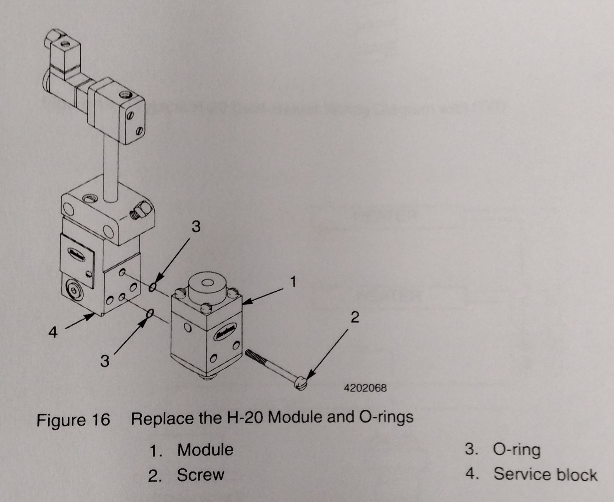
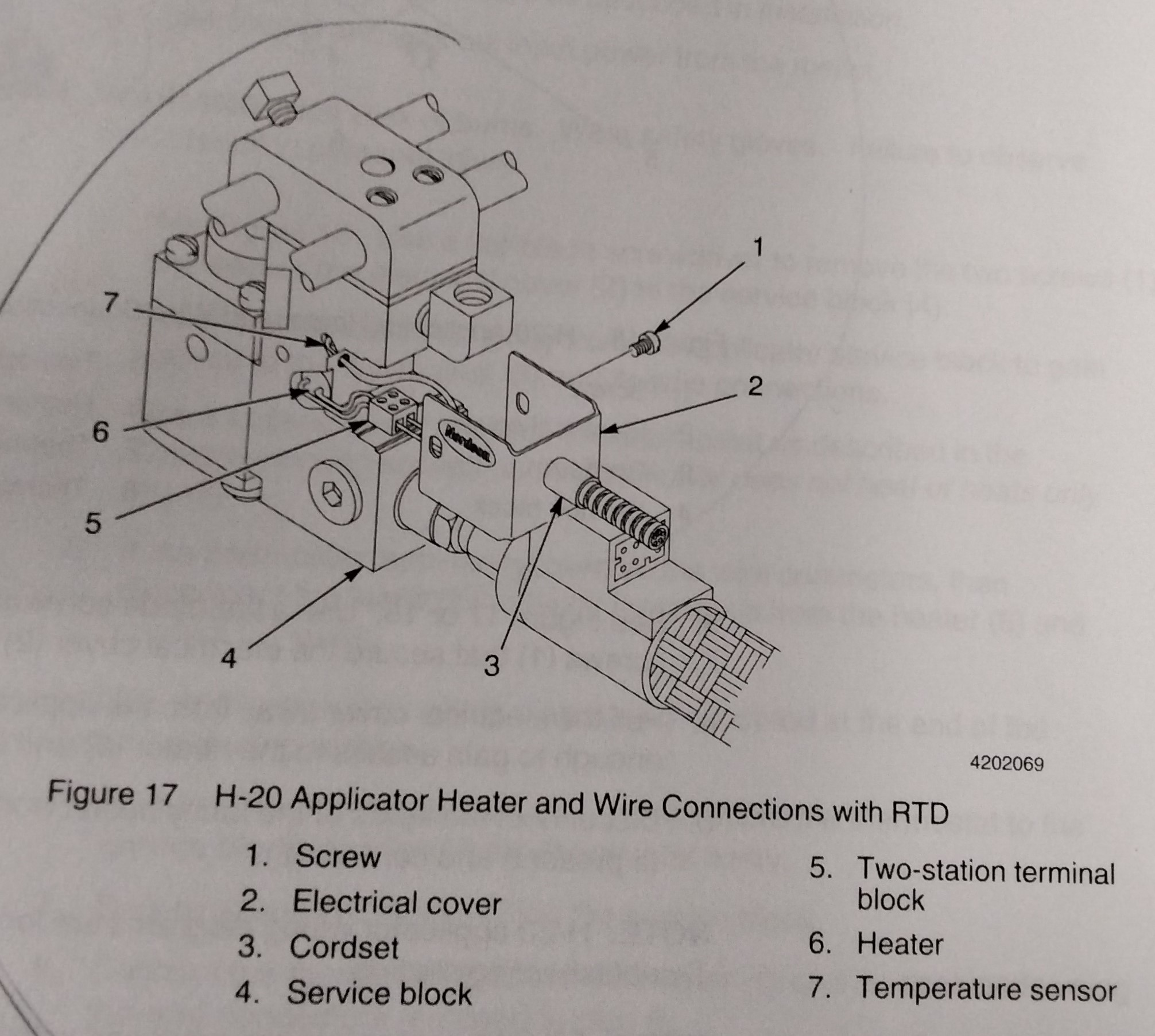
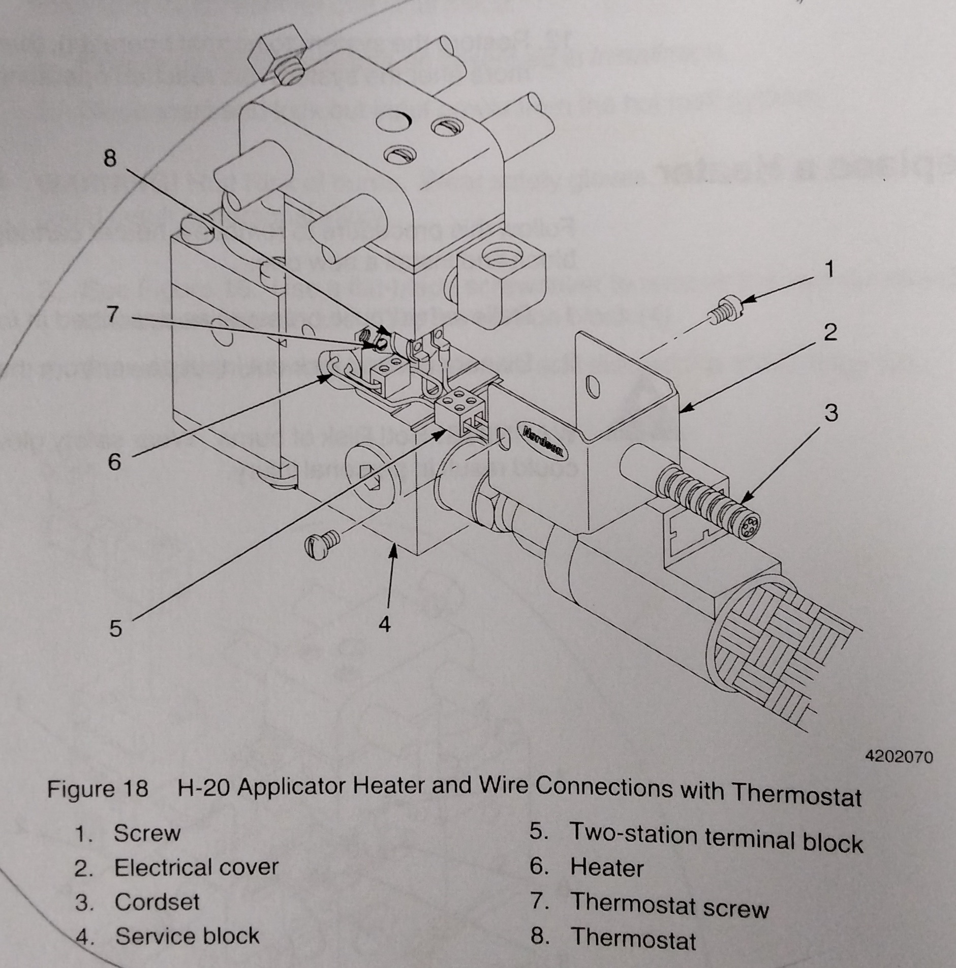
WARNING! Allow only personnel with appropriate training and experience to operate or service the equipment. The use of untrained or inexperienced personnel to operate or service the equipment can result in injury, including death, to themselves and others, and damage to the equipment. This part of the manual describes repair and replacement procedures for the Series H-20 automatic applicators. For maintenance procedures, such as filter flushing and filter cleaning, refer to "Maintenance". for melter maintenance procedures, refer to the melter manual. REPLACE A MODULE Follow this procedure to remove an H-20 module from the applicator service block and install another one in its place. 1. Relieve hydraulic pressure as described in "Installation". 2. Disconnect and lock our input power from the hot melt system. WARNING! Hot! Risk of burns. Wear safety gloves. Failure to observe could result in personal injury. 3.See Figure 16. Use a flat-blade screwdriver to remove the two screws (2) that secure the module (1) to the service block (4) 4. Remover the old module. Then remove and discard the old O-rings (3) 5. Wipe residual adhesive from the applicator service block surface that mates with the module. 6. Coat a new pair of O-rings (3) with O-ring lubricant and place them in their grooves in the applicator service body. 7. Trigger the applicator solenoid once or twice to clear any adhesive from the open air channel in the applicator service block (4). 8. Wipe adhesive from the applicator service block. 9. Apply a coating of anti-seize lubricant to the module screws (2) 10. Position the new module against the service block and secure it in place with the two screws. 11. Torque both screws to 2.6N-m (23 in. -Ib). 12. Restore the system to normal operation, then torque both the screws once more after the system has reached operating temperature. REPLACE A HEATER Follow this procedure to remove a heater cartridge from an H-20 service block and install a new one. 1. Relieve hydraulic pressure as described in "Installation". 2. Disconnect and lock out input power from the melter. WARNING! HOT! Risk of burns. Wear safety gloves. Failure to observe could result in personal injury. 3. See Figure 17 or 18. Use a flat-blade screwdriver to remove the two screws (1) that secure the electrical cover (2) to the service block (4). 4. Pull the electrical cover away from the applicator service block only enough to gain access to the heater (6) and its wire connections. 5.DIsconnect the leads of the faulty heater from the thermostat (8) (if present) and cordset (3). NOTE: H-20 applicator wiring diagrams are located at the end of the Troubleshooting section. NOTE: Filtered applicators are equipped with two heaters, non-filtered applicators have only one heater. Refer to Parts for H-20 applicator parts lists and illustrations. 6. Use an ohmmeter to check the heater for continuity as described in the Troubleshooting Section under "Applicator does not heat or heats only slightly ". No continuity means a faulty heater. 7. If the heater (6)tests faulty, remove it from the service block. NOTE: Heating and cooling cycles may cause the heater to become seized inside the bore in the service block. In this case, tap on a wooden dowel positioned against the flat face of the heater to force the heater out. 8. Insert the new heater (6) in its bore in the service block. 9. Connect the heater leads to the thermostat (8) (if present) and cordset (3). 10. Reinstall the electrical cover (2) with the enclosure screws (1). 11. Restore electrical power to the system., then resume normal operation. REPLACE A THERMOSTAT -1 1. Relieve hydraulic pressure as described in "Installation". 2. Disconnect and lock out input power from the meter. WARNING! Hot! Risk of burns. Wear safety gloves. Failure to observe could result in personal injury. 3. See Figure 18. Use a flat-blade screwdriver to remove the two screws (1) that secure the electrical cover (2) to the service block (4) 4. Pull the electrical cover away from the applicat
5. Use a voltage tester to check the thermostat as described in the Troubleshooting section under "Applicator does not heat or heats only slightly." 6. If the thermostat tests faulty, remove the wire connectors then disconnect the leads of the faulty thermostat from the heater (6) and cordset (3) leads. NOTE: H-20 applicator wiring diagrams are located at the end of the Troubleshooting section. 7. Remove the thermostat screws (7) that secure the thermostat tot he service block (4), then lift the thermostat away. 8. Secure a new thermostat (7) to the service block. 9. Connect the thermostat leads to the heater (6) and cordset leads using the wire connectors removed in step 6. 10. Reinstall the electrical cover (2) screws (1) 11. Restore electrical power to the system, then resume normal operation.
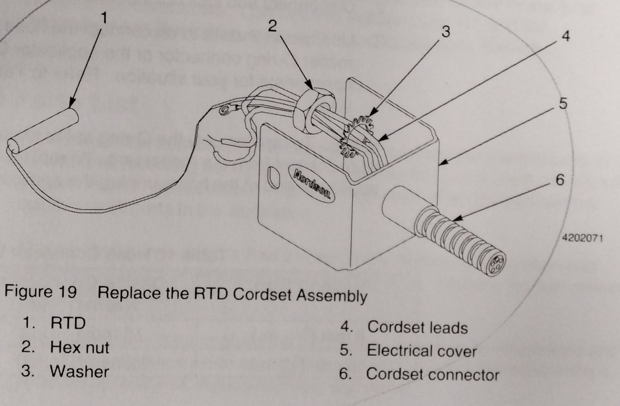
Follow this procedure to replace the cordset assembly: NOTE: Nordson offers a kit for replacement of a faulty RTD only. However, this requires cutting the sensor leads and using wire connectors which may adversely affect sensor accuracy. 1. Relieve hydraulic pressure as described earlier in this section. 2. Disconnect and lock out input power from the melter. WARNING! Hot! Risk of burns. Wear safety gloves. Failure to observe this warning could result in personal injury. 3. See Figure 17. Use a flat-blade screwdriver to remove the two screws (1) that secure the electrical cover (2) to the service block (4). 4. Pull the electrical cover away from the applicator service block to gain access to the wire connections. 5. Disconnect the heater leads from the cordset leads. NOTE: Refer to the H-20 applicator wiring diagrams located in Troubleshooting. NOTE: Filtered applicators are equipped with two heaters, non-filtered applicators have only one heater. Refer to the "Parts" section for H-20 applicator parts lists and illustrations. 6. Disconnect the ground wire from the applicator service block. 7. See Figure 19. Pull the RTD (1) from its bore in the applicator service block. 8. Pull the cordset away with the electrical cover (5) attached. 9. Remove the hex nut (2) and washer (3) from the old cordset connector (6),then remove the electrical cover. 10. Thread the new RTD and cordset leads (4) through the electrical cover, hex nut and washer. 11. Install the hex nut and washer onto the new cordset connector. 12. Connect the ground wire to tis terminal on the applicator service block. 13. Connect the heater leads to the new cordset heater leads. 14. Insert the new RTD into its bore in the applicator service block. 15. Install the electrical cover on the applicator service block. 16. Restore electrical power to the system, then resume normal operation.
1. Relieve hydraulic pressure as detailed earlier in this section. 2. Disconnect and lock out input power from the melter. 3. Use two wrenches to disconnect the hose swivel fitting from either the melter O-ring connector or the applicator O-ring connector, whichever is appropriate for your situation. Refer to Table 10 for the correct wench size. NOTE: To replace only the O-ring at the melter end of the hose, unplug the hose cordset from the melter unit. To replace only the O-ring at the applicator end of the hose, unplug the applicator cordset from the hose. TABLE 10 HOSE CONNECTOR WRENCH SIZES HOSE ID SIZE O-RING CONNECTOR WRENCH SIZE HOSE SWIVEL FITTING WRENCH SIZE 8mm (5/16 in.) 16 mm (5/8 in.) 18 mm (11/16 in.) 16mm (5/8 in.) 32 mm (1 1/4 in.) 32 mm (1 1/4 in.) 4. Remove the O-ring connector, then replace the old O-ring with a new one. 5. Install the O-ring connector. 6. Plug the applicator cordset back into its socket at the end of the hose or plug the hose cordset back into the melter electrical enclosure socket. 7. Restore electrical power to the melter, and bring it to operating temperature. 8. Use the two wrenches to connect the hose swivel fitting on to the O-ring connector. Do not overtighten the connection. 9. Check for leakage. Retighten the fittings as necessary. If no leaks occur, resume normal operation. NOTE: Severe leakage at a hose hydraulic connection can indicate the use of incorrect O-rings or missing or damaged O-rings. Check for correct parts or for missing or damaged O-rings.
Source: Ideal Cabinetry (Community Member)

