Mack | Mack ASET AC Diesel Engine - Regular Maintenance
Use this checklist for the cleaning and inspection of your unit injector. Regular maintenance helps in preserving your truck and ensuring that it performs at its best for a long period of time.
Mack | Mack ASET AC Diesel Engine - Regular Maintenance
Use this checklist for the cleaning and inspection of your unit injector. Regular maintenance helps in preserving your truck and ensuring that it performs at its best for a long period of time.
LUBRICATION SYSTEM MAINTENANCE FOR ASET™ ENGINES
Crankcase Breather Element Cleaning
[219 ER]
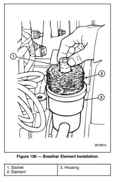
All ASET™ engines are equipped with a fiberglass-reinforced nylon crankcase breather element canister. The procedure for cleaning the element is as follows:
Note: A socket with the same diameter as the center tube in the breather housing will ease installation of the filter element. Insert the socket in the filter element and place the element and socket over the center tube. Then, slide the element onto the tube and remove the socket (Figure 106).
Oil Level Check
When checking oil levels, the vehicle must be parked on level ground and the units at normal operating temperature. Components must be filled to the correct level. DO NOT OVERFILL.
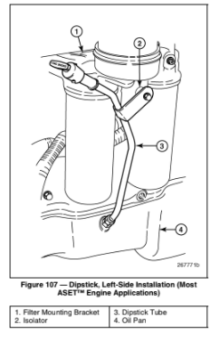
The left-side dipstick location shown in Figure 107 applies to most ASET™ engines. Early production AI/AMI engines and AI engines built with the traditional front water pump configuration still utilize the right-side dipstick location.
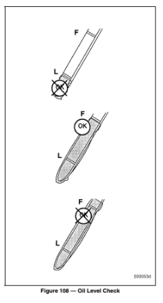
For accurate oil level readings, the dipstick must be inserted into the dipstick tube with the “L” and “F” markings facing upward. On conventional cabs, this will be with the finger-loop facing outboard, or away from the engine. On LE and MR models, the “F” and “L” marks must be facing up as the dipstick is inserted into the dipstick tube.
Oil and Filter Change Procedure
[219 EV]
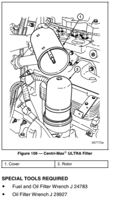
The ASET™ engines are equipped with improved spin-on type oil filters. The Centri-Max® ULTRA or ULTRA PLUS internally drained and vented filter design is taller and set in a cover housing with an integral oil fill port (Figure 109).
DISPOSABLE SPIN-ON OIL FILTER REPLACEMENT
Change oil and replace oil filters using the following procedure:
Note: Use of anything other than genuine MACK filters may cause damage and void the engine warranty. Change filters according to the recommended maintenance schedule.
CENTRI-MAX® ULTRA OR ULTRA PLUS OIL FILTER
[219 EV]
The following procedure applies for both the ULTRA and ULTRA PLUS filters. However, the ULTRA PLUS rotor bushing hole sizes and the mating shaft journals are smaller than those of the ULTRA filter. As such, the rotors are not interchangeable.
Note: Centri-Max® ULTRA PLUS filter assemblies may have a one-piece (early production) or two-piece (current production) spindle configuration. Both configurations, however, use the same ULTRA PLUS rotor.
Caution: Use the correct rotor kit for the centrifugal filter assembly application, 57GC2206 for Centri-Max® ULTRA and 57GC2231 for Centri-Max® ULTRA PLUS. For easy identification, the ULTRA PLUS rotor is black, whereas the ULTRA rotor is cream color. If the ULTRA rotor is used in an ULTRA PLUS application, the rotor bushings will be a very loose fit on the smaller diameter shaft and the rotor will not rotate, resulting in a non-functioning centrifugal filter.
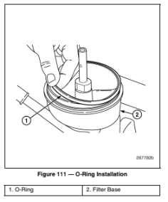
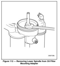
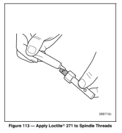
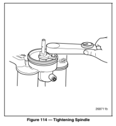
Centri-Max® ULTRA PLUS Spindle Replacement (If Required)
The Centri-Max® ULTRA PLUS with the two-piece spindle and new smaller diameter shaft became the standard for all ASETTM engines in the fourth quarter of 2003. This procedure covers only this latest style filter arrangement.
Note: Allow the Loctite® to cure for a minimum of one hour before starting and running the engine.
FUEL FILTER ELEMENT REPLACEMENT FOR ASET™ AC ENGINES
Primary/Secondary Fuel Filter Change
[231 BA]
SPECIAL TOOL REQUIRED
For engines produced before December 22, 2003, clean or replace the pre-pump filter screen and change the secondary fuel filter at each specified oil and filter change interval.
For current-production engines (December 22, 2003 and later production), change the chassis-mounted primary filter and replace the secondary filter on the supply pump at each specified oil and filter change interval. The pre-pump filter is no longer used and the port is plugged on current-production engines.
ASET™ AC FILTER DESCRIPTION
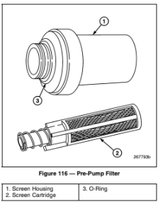
The pre-pump filter on the ASET™ AC engine, located at the bottom of the fuel supply pump, uses a screen cartridge to remove particulates that would damage the pump gears (Figure 116). The cartridge is fitted into a transparent housing that allows visual inspection for sediment in the trap. The cartridge housing is threaded onto the pump housing for easy removal for cleaning or replacement of the cartridge.
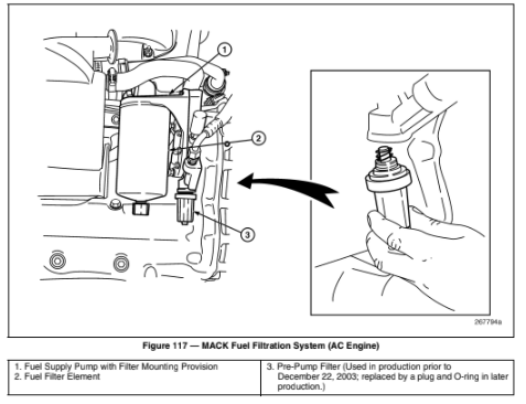
The high filtration primary spin-on fuel filter element (3–5 microns) used on CEGR engines is also located on the supply pump (Figure 117). It is mounted to a metric-threaded spud at the pump’s pressure outlet. The filter element is fitted with a fuel-drain port at the bottom.
Note: Because of ice buildup in the fuel system or fuel waxing which can clog fuel filters, it may be necessary to reduce the time or mileage interval between fuel filter changes during extremely cold weather.
Note: General field practice is to prime the fuel filters before installation. This practice can allow dirt to enter the outlet port of the filter if caution is not used. Use filtered fuel only when priming the filter. Prime through the series of small holes on the top of the filter. DO NOT prime the filter through the center hole.
PRE-PUMP FILTER CARTRIDGE CLEANING OR REPLACEMENT
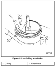
To remove, clean or replace the pre-pump filter cartridge (if so equipped):
SPIN-ON FUEL FILTER REPLACEMENT
To replace the spin-on fuel filter on the pressure side of the pump and the chassis-mounted primary fuel filter (if so equipped):
Caution: If priming the fuel system on an ASET™ AC engine becomes necessary, the only acceptable method is to use the hand primer pump located on the supply pump. DO NOT attempt to prime the fuel system by applying air pressure to the fuel tank or by using an auxiliary pump, as these methods may result in severe engine damage caused by fuel that leaked past the supply pump seal into the crankcase.
COOLANT CONDITIONER ELEMENT REPLACEMENT FOR ASET™ ENGINES
Coolant Conditioner Replacement
[215 LD]
SPECIAL TOOLS REQUIRED
The conditioner element is replaced as follows:
All ASET™ ENGINES
OIL COALESCING AIR FILTER REPLACEMENT
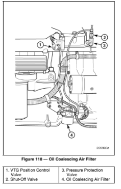
Engines produced after May 4, 2004 have an oil coalescing air filter incorporated into the air line supplying the control valve to prevent oil condensation and possible “coking” inside the VTG position control valve. This filter is mounted on a bracket at the lower side of the cylinder block, to the rear of the oil filters (Figure 118). The filter must be changed at each B, C and D inspection interval (every other engine oil change interval). Procedures for replacing the spin-on filter are as follows:
DRIVE BELT REPLACEMENT AND TENSIONING FOR ASET™ AC ENGINES
[216 AA]
General Information
The service life of the poly-V belts is considerably improved over other systems and allows the use of higher horsepower cooling fans. All ASET™ engines are equipped with poly-V belt systems.
ASET™ AC ENGINES
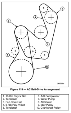
In the AC dual poly-V drive belt arrangement, the fan drive is driven directly from the crankshaft pulley by a 10-rib poly-V belt. In turn, the water pump, alternator and the air conditioning compressor (if equipped) are driven off the fan-drive hub by a 6-rib poly-V belt (Figure 119). Two automatic tensioners are used, one for the fan drive and one for the accessory drive.
Note: Refer to ASET™ AC ENGINE DRIVE BELT SPECIFICATIONS section for belt sizing and part numbers.
Note: Refer to ASET™ AC SCHEMATIC and ROUTING DIAGRAMS section for accessory drive belt routings.
The tensioner for the crankshaft-to-fan drive hub is mounted to the timing gear cover. This tensioner spring loads in a counterclockwise direction to apply load to the belt. The accessory drive belt tensioner is mounted on the new water pump assembly. There are two possible mounting locations for this tensioner depending on the chassis model and if equipped with an air conditioner. The tensioner spring-loading direction (clockwise with A/C or counterclockwise non-A/C) for applying load to the belt is determ
Automatically Tensioned System
INSTALLATION
Swing the tensioner to the fully sprung position and, without force, place the belt over the pulleys. Do not allow the tensioner to snap against its stops. Do not pry the belt over a pulley.
TENSIONING
No tensioning adjustment is required. Once the tensioner is released against the belt, the belt is tightened to optimum tension automatically at all speeds and loads.
MAINTENANCE
The condition of the belt and tensioner should be checked when performing preventive maintenance inspections A, B, C and D as outlined in the Maintenance and Lubrication manual, TS494. Belt tension levels need not be checked as long as the tensioner is in good condition and there is no evidence of a loose belt.
Source: MaintainX (Community Member)

