A battery from the factory will require approx. 5 - 10 charge and discharge cycles to reach its full capacity
A battery is considered to be technically discharged when it has reached 20% residual capacity. For example, a battery with a 500 amp hour capacity has an actual available output of 400 amp hours.
In addition, the effective output will depend on the discharge speed, which in turn is affected by the particular truck application.
The battery discharge indicator must therefore be set in accordance with the truck's particular application conditions.
The battery discharge indicator controls the lift cutout system. The lift cutout system is designed to prevent the battery from being operated to the point where is fully discharged.
If the battery is constantly discharged to below 20% of residual capacity it will be damaged.
If the lift cutout system is activated above 20% of the battery's residual capacity the battery will not be damaged, but the truck's maximum operating time under a single battery charge will not be attained.
The lift cutout system should therefore be activated as close to 20% of the battery's residual capacity as possible. If at all, it may be slightly above 20%, but never below.
The acid density is a very reliable indicator of the charge status of a lead acid battery.
However, since it is unrealistic to continually measure the acid density of a truck battery to an industrial standard, the battery voltage is used to determine the charge status over longer journeys.
To adapt the BDI to the battery used and the truck's specific application profile, you need the battery manufacturer's data sheet.
The values you require are the density of the electrolyte for an 80% discharged battery (20% battery residual capacity) and for a fully charged battery (100% battery capacity).
Finally, via the potentiometer on the back of the BDI the display is set to the actual discharge terminal voltage of the battery at 20% residual capacity.
The factory default setting of the battery discharge indicator is "N" (any setting from K to U is possible).
Fully charge the battery as indicated by the battery manufacturer in the operating instructions.
Measure the acid density in accordance with the battery manufacturer's maintenance instructionsto check if the battery is actually 100% charged.
Faulty battery cells will make calibration impos- sible.
Operate the truck as usual under normal operating conditions until the battery is empty: both LEDs of the BDI will flash and the lift cutout system will be triggered.
Leave the battery for at least 10 to12 hours (one hour at the very minimum!).
After this interval measure the acid density on at least three different battery cells. The smallest recorded value is the one you need.
Compare the recorded density with the density specified by the manufacturer for an 80% discharged battery (20% residual capacity).
If the battery is more than 80% discharged (less than 20% residual capacity), set the potentiometer on the back of the BDI to direction K.
If the battery is less than 80% discharged (more than 20% residual capacity), set the potentiometer on the back of the BDI to direction U.
Charge the battery again and then check the calibration.
Pulling the battery connector on the red knob at the top of the truck completely disconnects the power supply to the truck.
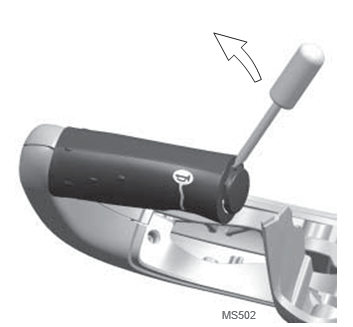
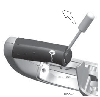
Using a small flat screwdriver lever out the handle protective cap (see Fig. MS502)
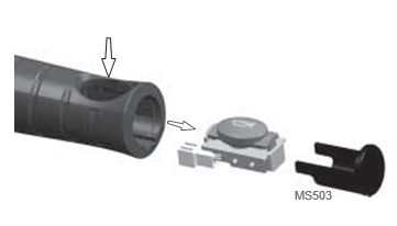
Simply press the horn switch inward and pull it out of the handle (see Fig. MS503). Disconnect the plug connector from the switch.
Re-install the switch unit (see SWITCH UNIT section in this chapter) and carry out a functional test.
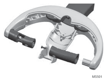
Unscrew the internal M5 Torx® screw (see Fig. MS501) and pull off the handle.
Re-install the switch unit (see SWITCH UNIT section in this chapter) and carry out a functional test.
The raise (RAS) and lower (LOS) switches are activated via rocker switches in the tiller head.
The rocker switches act on switches fitted on the tiller hydraulic PCB.
The switches are physically locked in pairs so that they cannot be pressed together at the same time.
The raise (RAS) switch activates the pump contactor (P), which cause the pump to start.
The lower (LOS) switch applies voltage to the solenoid (SV) which causes the solenoid to open.
Travel Switch (Both Direction)
The Fast / Slow travel switch (HSS) is activated via a toggle switch (Rabbit / Turtle symbol) on the multitask handle head.
The switch signal to the traction controller is used to change between the high and slow speed ranges.
The safety reverse switch (SAS) is activated via the switch cap at the end of the tiller head: the traction controller immediately changes from forward to reverse travel when the SAS is activated.
The signal for normal travel to the traction controller is simultaneously inter- rupted.
Depending on the traction controller setting the truck either travels for a given time, or provided the switch is pressed, travels in reverse.
The 3 springs for return function are located on the rotary axle of the multitask handle.
The inner, offset end of the springs fits in the longitudinal slot of the axle.
The external end which is also offset exerts upward pressure on the multitask handle.
The springs can be easily accessed for lubrication by removing the panel from the knuckle.
Disconnect the battery (emergency disconnect).
Secure the truck to prevent it from rolling away.
Set multitask handle (1) to zero/rest position (1).
Drive out the dowel pin on the left hand side.
Drive in the dowel pin on the right hand side by rotating the axle as far as possible using a face spanner.
Multitask handle (1) in zero position.
Record the position of the axle.
Drive out the roll pin. The de-pressurised springs should rotate the axle.
Set the multitask handle to the lowest position
If the axle has still not turned, it is clearly fixed in its position and must be moved with the aid of a face spanner. Rotate the axle, seen from the left hand side, approx. 20° anticlockwise from the fixed position.
Drive the axle as far out to the right hand side so that the 3 springs can be removed.
Push the 3 springs onto the axle. The inner, offset end must insert into the axle groove. A strap wrapped around the inner end of the first spring to be inserted can prove useful when inserting the other springs.
Drive the axle into position.
Set the multitask handle to the upper limit.
Using a roll pin fix the axle to the left hand side (right hand side if necessary). To do this, rotate the axle as far as necessary.
Disconnect the battery (emergency disconnect).
Jack up the truck.
Remove the front panel and knuckle panels.
Remove all 6 mounting screws (12) of the knuckle (6) and remove the multitask handle and its support. Make sure that no wires are damaged in the process.
Disconnect the drive unit wires.
Using a rubber hammer gently knock the flange (17) and the drive unit down out of the chassis.
The lower conical roller bearing together with the inner ring and the seal (14) remain on the flange.
Remove the lower conical roller bearing to-gether with the inner ring and the seal (14) from the flange.
Lift out the upper conical roller bearing together with the inner ring and the seal (14).
Drive out the outer rings (16) of both bearings from the chassis.
Prior to installation make sure that the surfaces are clean and burr-free.
Refit all wire connections without twisting them.
Torque the knuckle mounting screws (12) to 49 Nm.
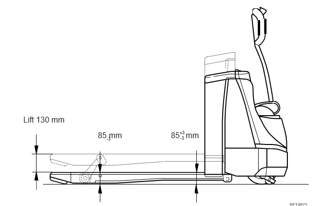
Lower the fork fully. The lifting joint (25) stop should match the fork tines (see Fig. M1468). If not, adjust fork height as desribed:
Raise lifting equipment.
Unscrew counter nuts (14) from connecting rod
Turn connecting rod (13) on hex. head.
Lower lifting equipment and check lifting joint stop.
Repeat the above steps until the stop setting is right when the fork is lowered.
Tighten counter nuts (14).
Repeat procedure on second fork tine.
Measure the fork height above the lift joint pivot point (left hand measuring point in Fig. M1465). The height should not exceed 83mm.
Measure the fork height at the fork carriage rear wall (right and measuring point in Fig. M1465).
The height should not exceed 89mm.
The measurement on the fork carriage rear wall must be equal to or greater than that at the fork tip.
Hydraulic Lines and Connections