Nordson PURBlue 4 Adhesive Melter
Customer Product Manual Part 1098452_04
Issued 11/2013
This document contains important safety information. Be sure to read and follow all safety information in this document and any other related documentation.
Nordson PURBlue 4 Adhesive Melter
Customer Product Manual Part 1098452_04
Issued 11/2013
This document contains important safety information. Be sure to read and follow all safety information in this document and any other related documentation.
PREVENTATIVE MAINTENANCE TASKS Table 5-1 describes the preventative maintenance tasks required to keep PURBlue 4 melters operating within their specified limits and to prevent equipment malfunctions. For information about maintaining optional equipment that was supplied by Nordson, refer to the instructions provided with the equipment. If the melter stops operating or is operating incorrectly, refer to Section 6, "Troubleshooting", for information about diagnosing common problems and performing corrective maintenance.
PREVENTATIVE MAINTENANCE TASKS
TASK FREQUENCY REFERENCE ---------------------------------------------------------------------------------------- Relieving system Before performing any Relieving System Pressure pressure. maintenance task that requires opening a hydraulic connection or port Cleaning the exterior of Daily Cleaning the melter Melter, hoses, and guns Cleaning the hopper, Weekly, or as needed Cleaning the Hopper and Melt melt plate, reservoir, depending on the Plate, Cleaning the Reservoir and piston and level sensor adhesive type Level Sensors, and Cleaning the probes Piston. Cleaning or replacing the Depending on dust electrical enclosure fan accumulation daily if filter necessary. Calibrating sensors As needed throughout the Calibrating the Hopper-Empty life of the melter (sensors Sensor or Calibrating the Level are factory-calibrated) Sensors. Calibrating the pump As needed throughout the Calibrating the Pump Speed speed display. life of the melter (the Display. pump speed display is factory calibrated)
RELIEVING SYSTEM PRESSURE
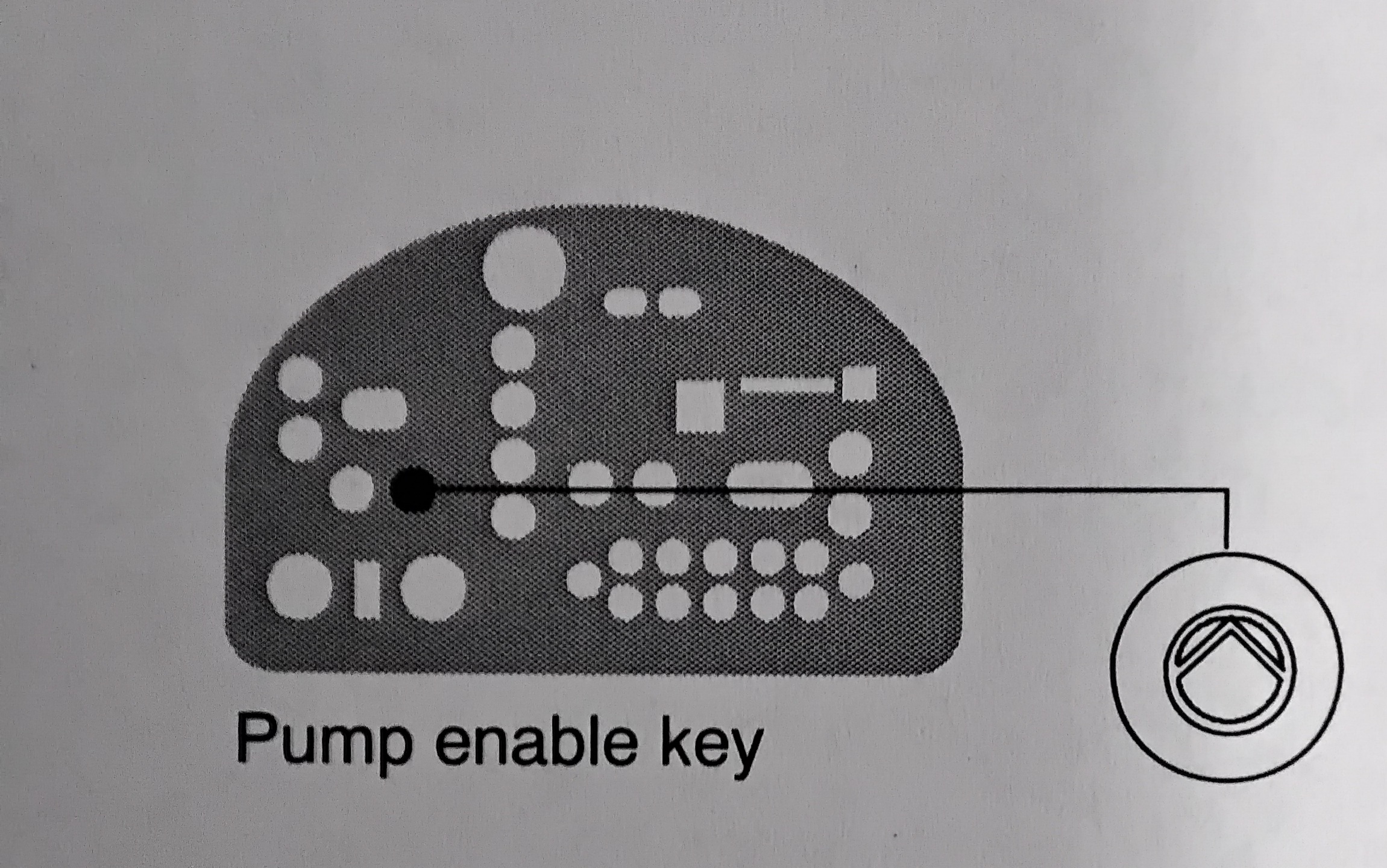
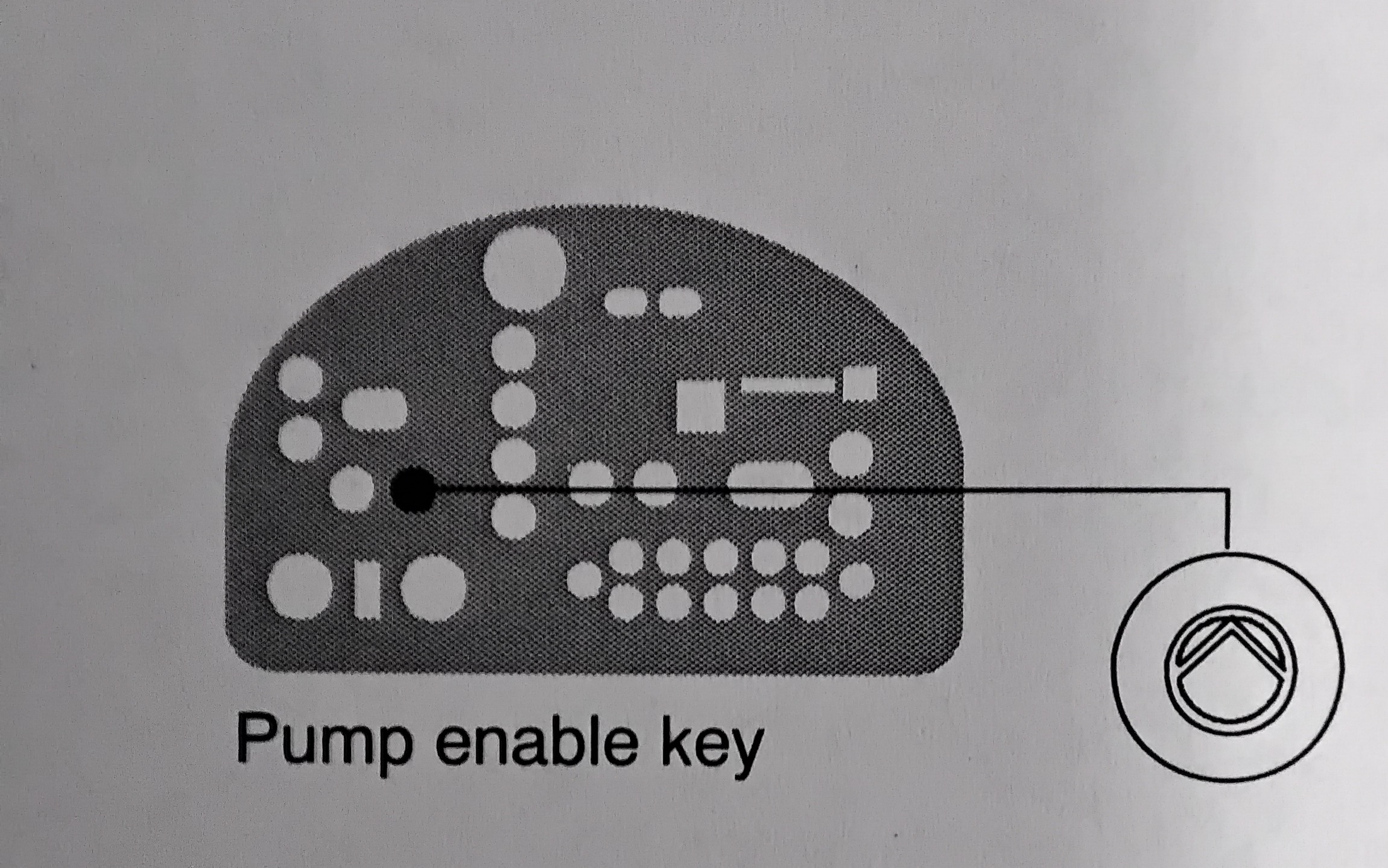
Before disconnecting any hydraulic fitting or opening any pressurized port, always complete the following procedure to safely relieve hydraulic pressure that may be trapped inside the melter, hoses, and guns. To relieve system pressure 1. Press "PUMP ENABLE" key to stop the pump. 2. Trigger the guns until hot melt no longer flows from the guns.
LOCKING OUT EXTERNAL COMMUNICATIONS
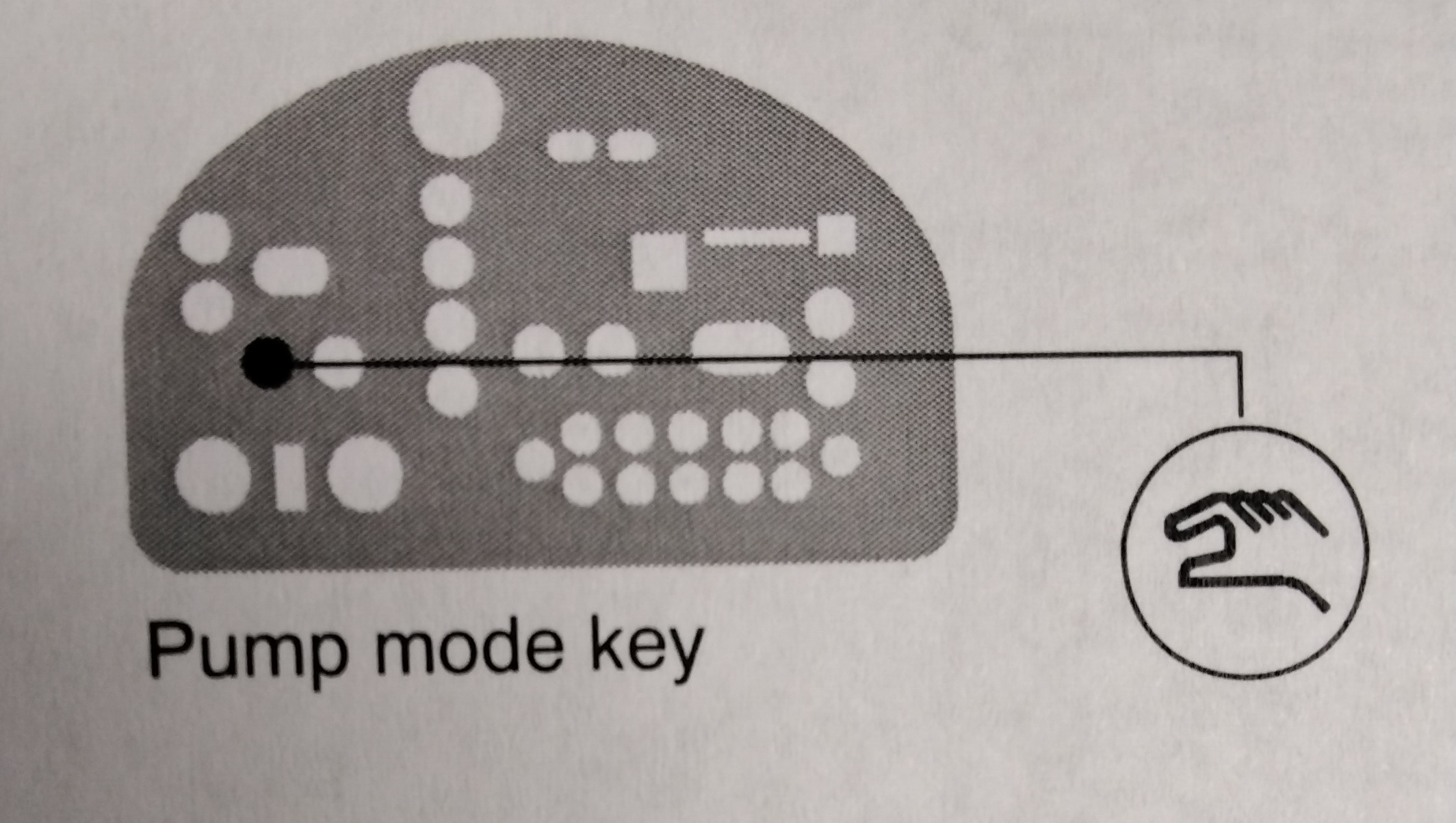
WARNING! Disable external inputs and fieldbus communications with the melter before performing maintenance. Failure to disable external inputs or fieldbus communications with the melter can result in personal injury due to unexpected operation of the melter while performing maintenance. To lockout external communication with the melter 1. Ensure that the PUMP MODE key LED is on. 2. Set the control option for parameter14 to 1 (enabled). 3. When the service activity is complete, return parameter 14 to 0 (Disabled). Refer to "Setting Up the melter" in Section 3, Installation, for information about changing operating parameters.
FLUSHING THE MELTER
Flush the melter at the following times to remove residue: - Before first-time operation of new melter. - Whenever the adhesive type is changed. - If a PUR adhesive is being used, before a melter shutdown that will last longer than two days. WARNING! Risk of burns! New melters contain a small quantity of low-viscosity test fluid. Test fluid may splatter when discharged under high pressure. Before flushing the melter, ensure that the PVC is set to low pressure. Process a minimum of one reservoir volume of hot melt or flushing material through the melter. hoses, and applicators.. At some point, set the pressure control to a low value and close the applicator (s) to flush the pressure control recirculation loop.
CLEANING THE MELTER
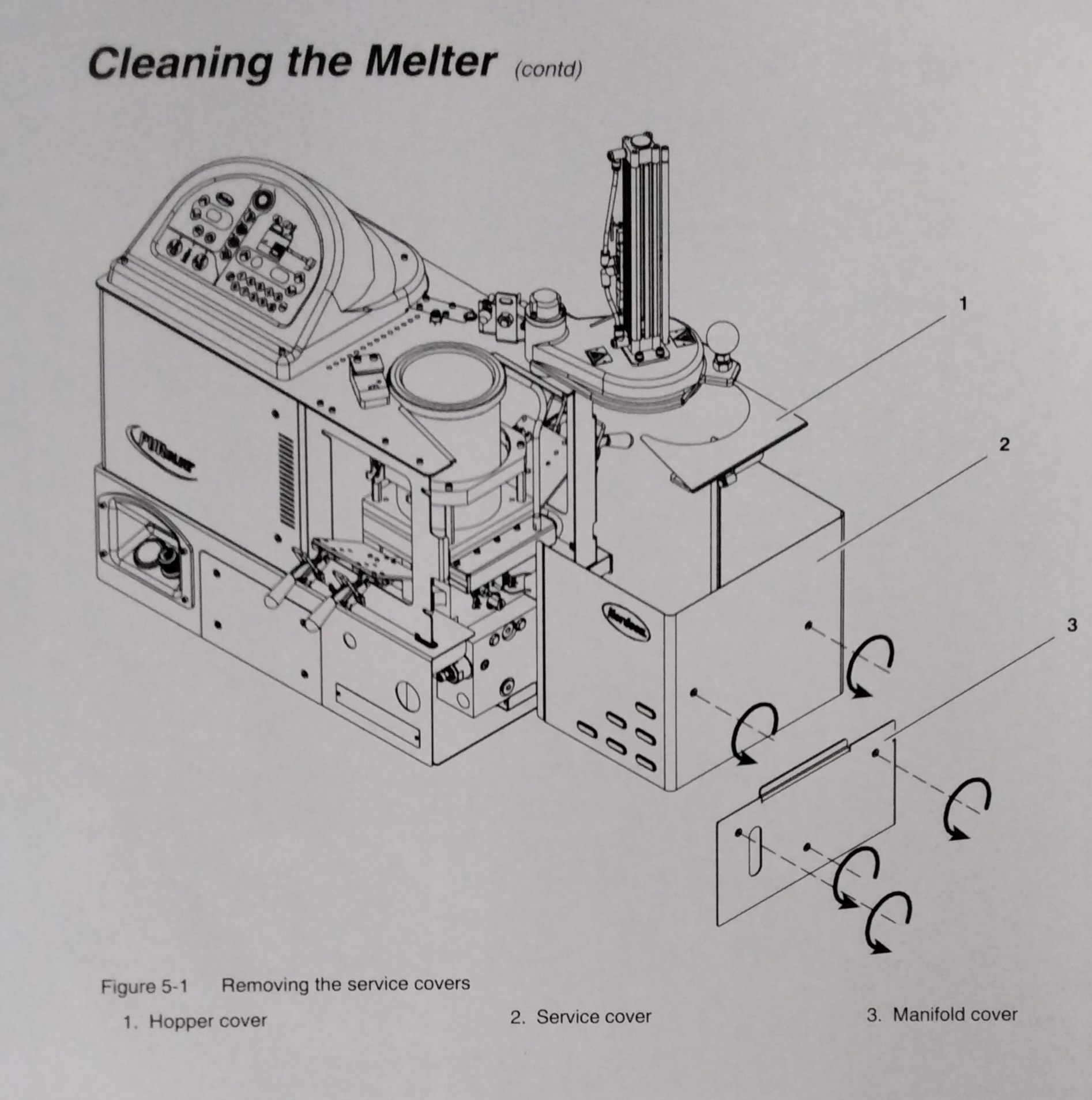
To prevent components from overheating due to heat build-up or loss of air circulation, regularly remove any hot melt that collects on the exterior of the melter, hoses, and, guns. If hot melt inadvertently spills inside the melter's interior spaces, the side covers can be removed in order to clean out the spilled hot melt. WARNING! Risk of electrocution and fire! Do not clean the melter with a direct stream of water or steam. Use only water or an appropriate, non-flammable cleaning solution that is applied using a clean cloth. Cleaning the melter using a direct stream of water or steam or a flammable solvent can result in property damage and personal injury, including death. TO CLEAN THE EXTERIOR OF THE MELTER: - Use only cleaning compounds that are compatible with polyester. - Apply cleaning compounds using a soft cloth. - Do not use pointed or shard tools to clean the exterior surface. TO REMOVE AND REPLACE THE SERVICE COVERS See Figure 5-1 1.De-energize the melter. Refer to Section1, "Safety" 2. Use a 4-mm (5/32-in) hex-head wrench to turn the 1/2-turn fasteners on each cover counterclockwise. 3. Disconnect all ground wires from the covers. 4. Lift the covers out of the melter's frame. 5. Reverse steps 2-4 to reinstall each cover. TO CLEAN THE ELECTRICAL ENCLOSURE: - After covers are removed, inspect the fan area and ensure that the air flow path for both side covers is clear. Remove excessive dust from inside the cabinet.
CLEANING THE HOPPER AND MELT PLATE
WARNING! Risk of injury. Wear proper gear. 1. Open the lid. CAUTION! Risk of equipment damage. The inside of the melter is release coated. Do not use metallic tools or wire brushes to clean the reservoir. 2. Wipe/remove any residual hot melt from the inside of the hopper and top of the melt plate. When the melter is cool, adhesive can typically be peeled from the release- coated parts. If the adhesive cannot be peeled off, heat the melter to the softening point of the adhesive and use a wooden or plastic scraper to remove the adhesive. 3. Remove all debris from the flat portion of the outer diameter of the melt plate. NOTE: It is particularly important to remove the adhesive from the flat portion of the outer diameter of the melt plate. This surface must be clear so that a good seal with the adhesive slug bag is possible. 4. Restore the system to normal operation.
CLEANING THE RESERVOIR AND LEVEL SENSORS
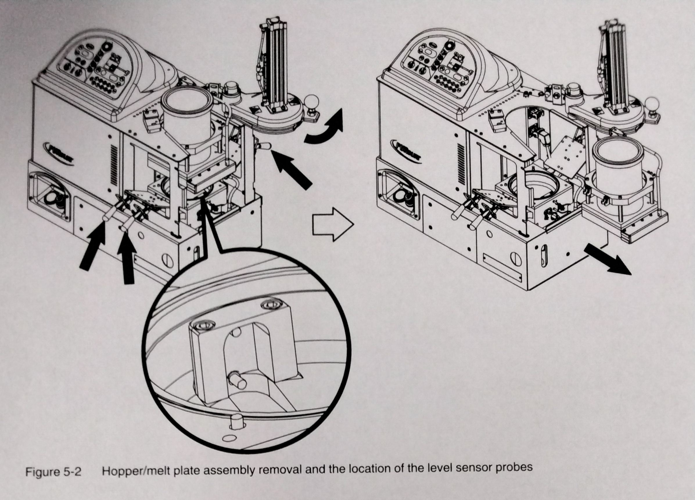
NOTE: If you are using a flushing material to clean the reservoir, ensure that the material is compatible with both the previous adhesive and the new adhesive, if applicable. 1. Operate the melter normally until the reservoir is empty. 2. Press the "PUMP ENABLE" key to stop the pump. 3. Allow the melter to cool to the temp recommended by the manufacturer of the adhesive or flushing material. 4.Remove the service covers. Refer to "To Remove and Replace Service Covers" earlier in this section as needed. 5. Disconnect the melt plate heater. 6. See Figure 5-2. Disengage the four hopper/melt plate assembly clamps. 7. Lift the hopper/melt plate assembly above the clamps and remove it through the open side of the melter. 8. If the adhesive is cool, try to peel it from the release-coated parts. If the adhesive is hot, use a wooden or plastic scraper to remove it. 9. See Figure 5-2. Clean the melt demand and reservoir empty sensor probes at the back of the reservoir. 10. Restore the system to normal operation.
CLEANING THE PISTON
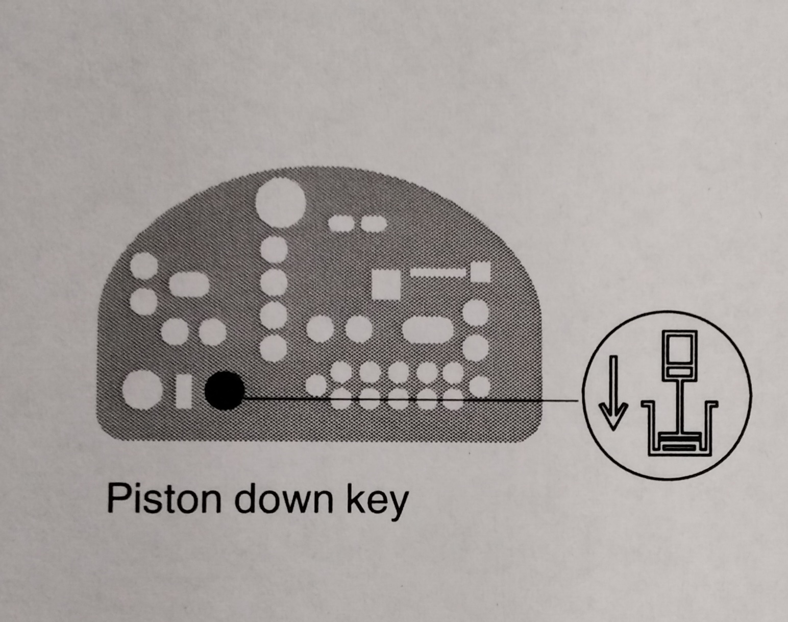
1. Operate the melter normally until the reservoir is empty. 2 .Press the "PUMP ENABLE" key to stop the pump. 3. Allow the melter to cool to the temp recommended by the manufacturer of the adhesive or flushing material. 4. Remove the service covers. Refer to "To Remove and Replace Service Covers" earlier in this section. 5. Disconnect the melt plate heater. 6. See Figure 5-2. Disengage the four hopper/melt plate assembly clamps. 7. Lift the hopper/melt plate assembly above the clamps and remove it through the open side of the melter. WARNING! Risk of personal injury. Keep hands away form the moving piston. 8. Close the lid. 9. Use the manual cylinder override on the top solenoid valve to lower the piston. 10. If the adhesive is cool, try to peel it from the release-coated parts. If the adhesive is too hot, use a wooden plastic scraper to remove it. 11. Restore the system to normal operation.
CALIBRATING THE HOPPER-EMPTY SENSOR
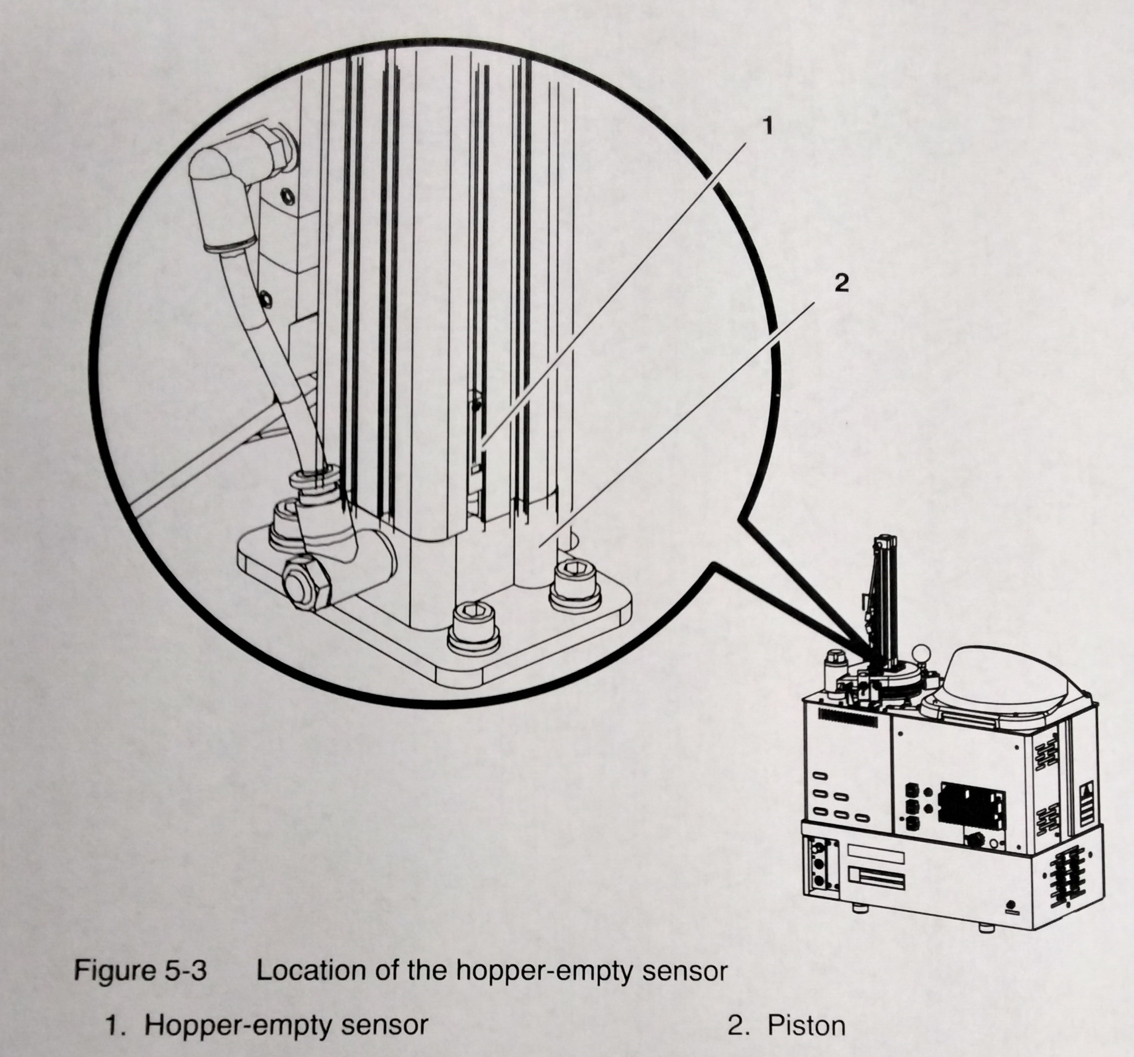
The melter is shipped with the hopper empty sensor calibrated for standard PUR adhesive. If recalibration becomes necessary, follow this procedure. See Figure 5-3 1. Operate the melter normally until the reservoir is empty, but leave the empty foil bag in place in the hopper. 2. Loosen the hopper-empty sensor (1) and move it to the lowest position on the piston. (2) 3. Move the sensor up until its LED illuminates and then secure the sensor at this location.
CALIBRATING THE LEVEL SENSORS
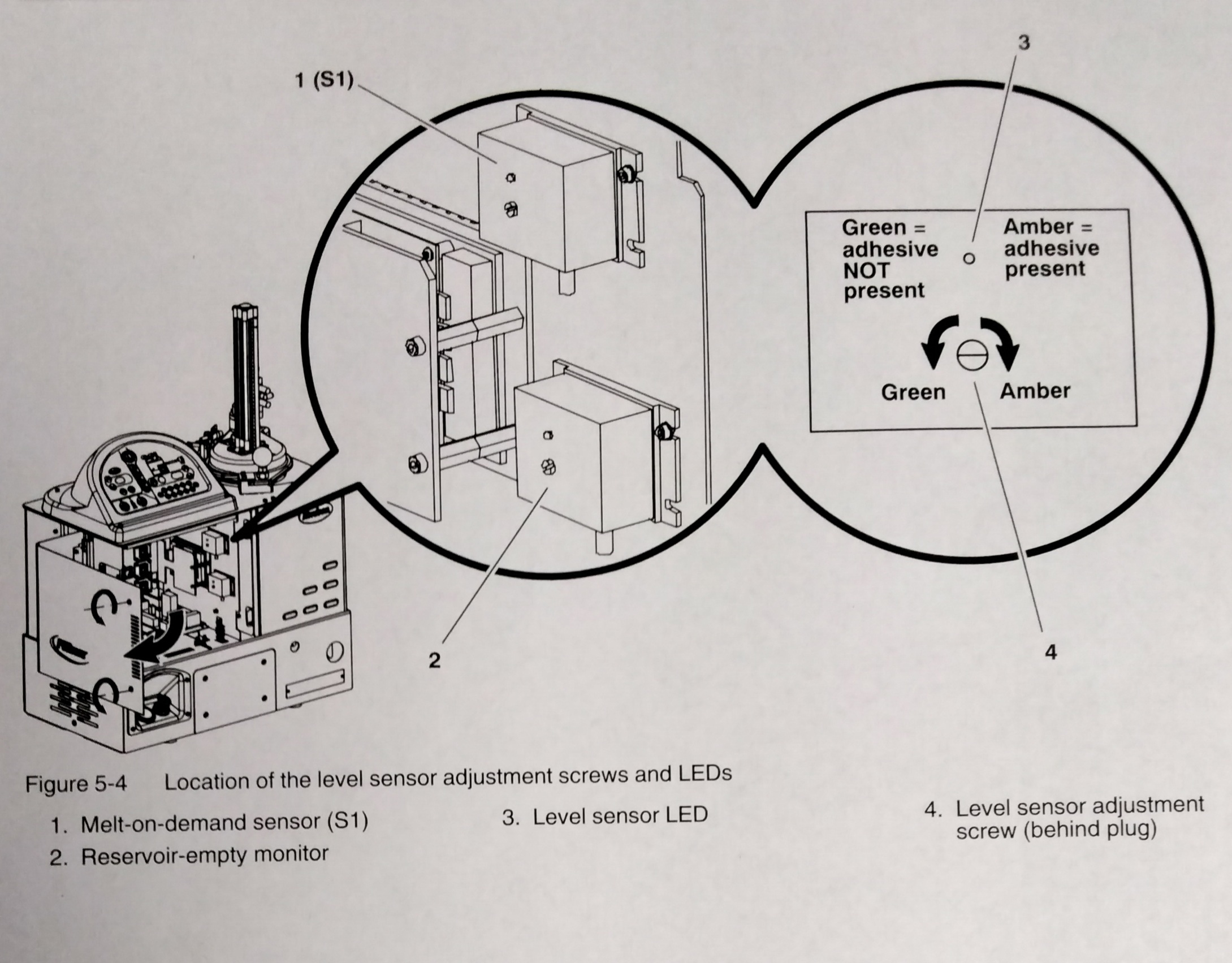
The melter is shipped with both level sensors calibrated for standard PUR adhesive. If recalibration becomes necessary, follow this procedure. 1. Operate the melter normally until the reservoir is empty. If the slug in the hopper is not empty, lift out the solid slug before pumping the adhesive from the reservior. 2. Remove all debris or cured adhesive from the sensor probes. Refer to "Cleaning the Reservoir and Level Sensors" earlier in this section, then return here to continue. 3. Ensure that the melter switch is on. 4. See Figure 5-4. Open the electrical enclosure and locate the two sensor amplifiers (items 1 and 2 in Figure 5-4) WARNING! Risk of equipment damage, personal injury, or death. This procedure requires you to perform work inside the electrical enclosure with the power on. Follow electrical safety procedures and observe all high-voltage indicators. 5. Remove the plugs that cover the sensor adjustment screws. 6. Turn each adjustment screw as follows: - clockwise until the LED turns yellow, - counterclockwise until the LED turns green - counterclockwise two(2) additional turns. NOTE: When a LED turns yellow, the system believes that adhesive is present. Because we know that adhesive is not present, turning an adjustment screw counterclockwise until LED turns green and then adding an additional two (2) counterclockwise turns calibrates the sensors.
CALIBRATING THE PUMP SPEED DISPLAY
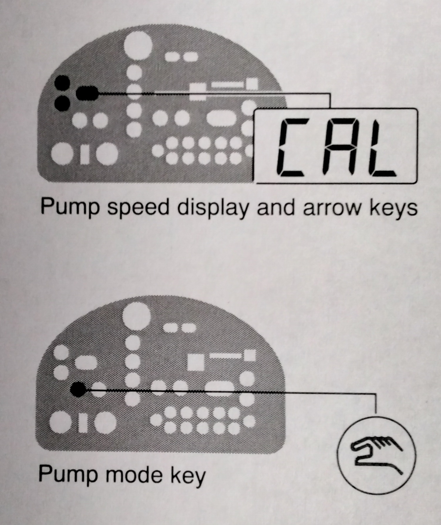
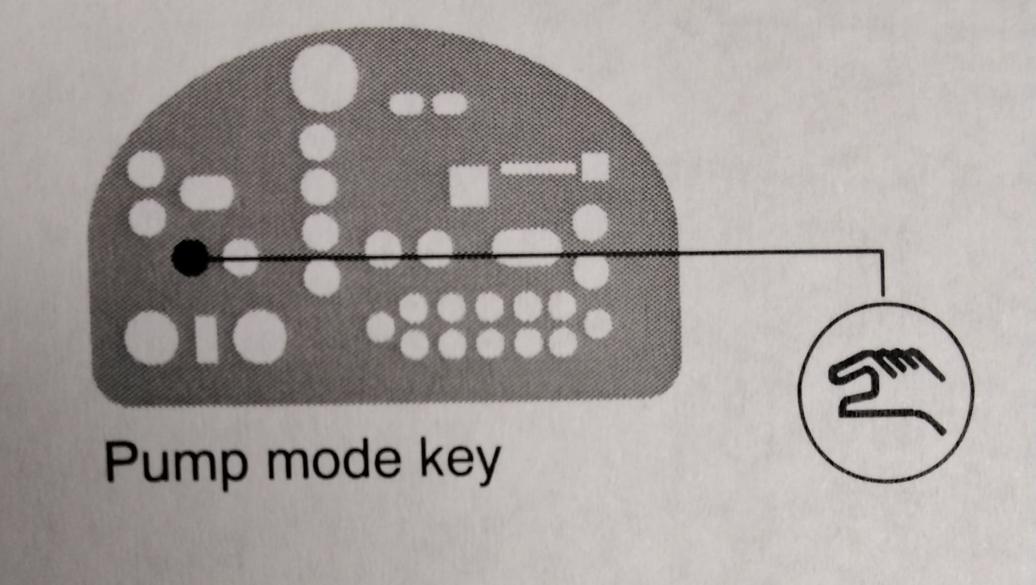
The melter is shipped with the pump speed display calibrated to show the pump rpm. If recalibration becomes necessary, follow this procedure. 1. Ensure that the motor is running at 50 percent speed or higher. 2. Press and hold both PUMP SPEED ARROW keys 3. When the motor control display indicates CAL. release the keys. 4. Enter the actual pump rpm. 5. Press the PUMP MODE key.
TROUBLESHOOTING
WARNING! Allow only personnel with appropriate training and experience to operate or service the equipment. The use of untrained or inexperienced personnel to operate or service the equipment can result in injury, including death, to themselves and others, and damage to the equipment. This section provides quick-reference information for diagnosing melter faults and pump operating variables as well as comprehensive melter diagnostic information that is provided in flowchart format. If you cannot resolve the problem using the troubleshooting flowchart, contact your Nordson representative for technical assistance.
SAFETY
- Never disconnect cables from, or reconnect cables to, any circuit board while the melter is energized. -Before breaking any hydraulic connection, always relieve system pressure. Refer to "Relieving System Pressure" in Section 5 "Maintenance" -Refer to the safety information provided with optional equipment.
TROUBLESHOOTING MELTER FAULTS
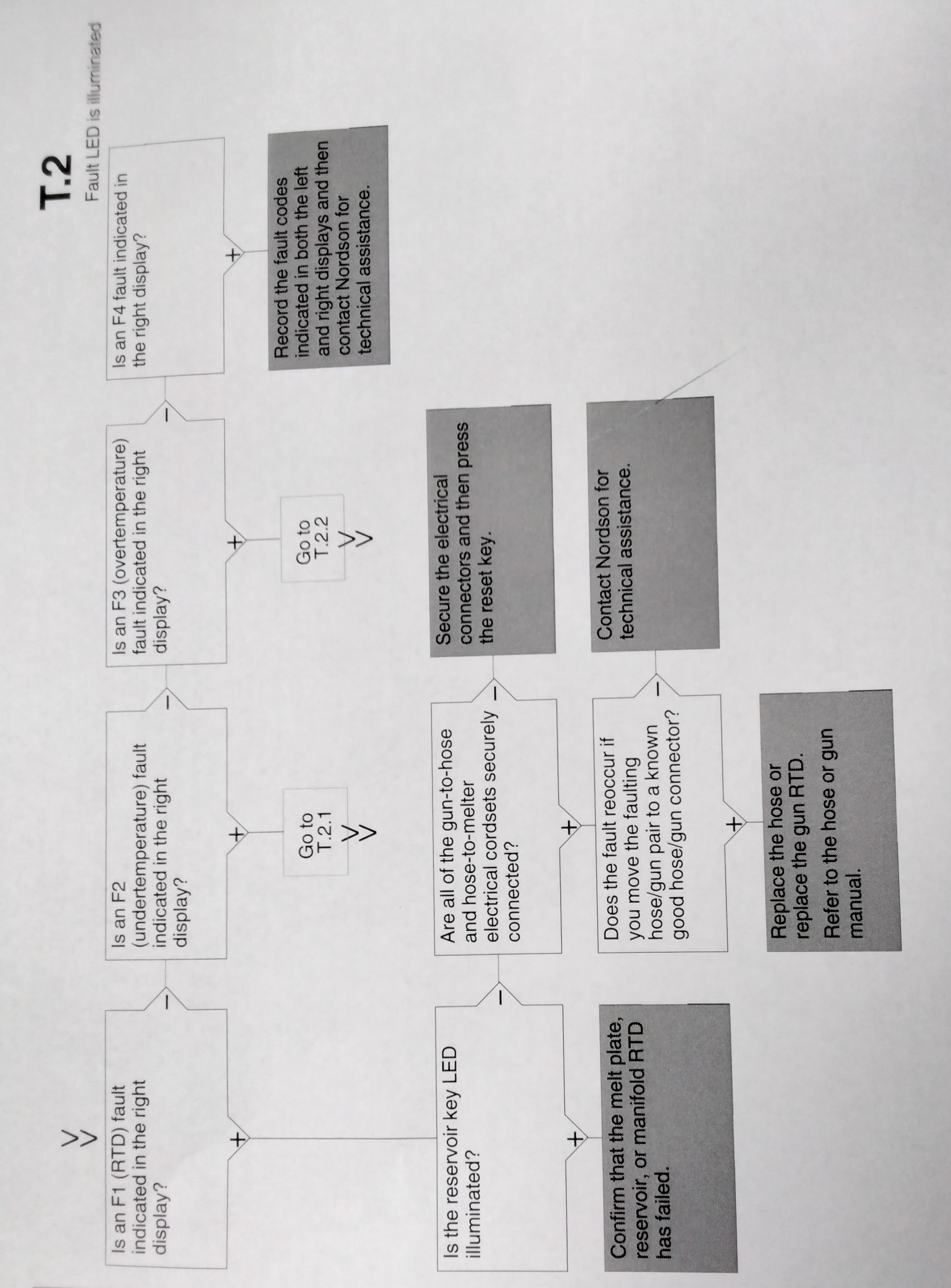
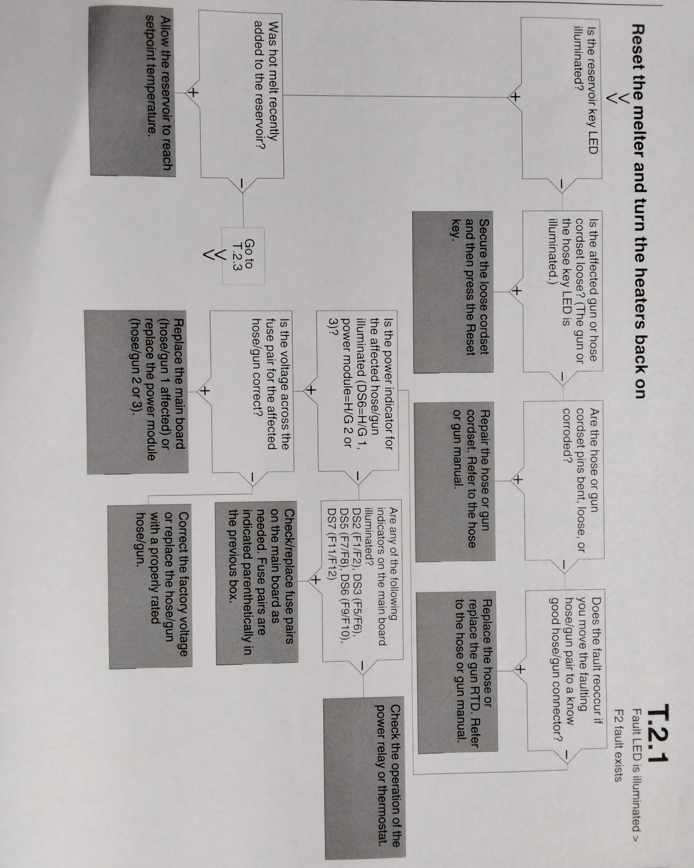
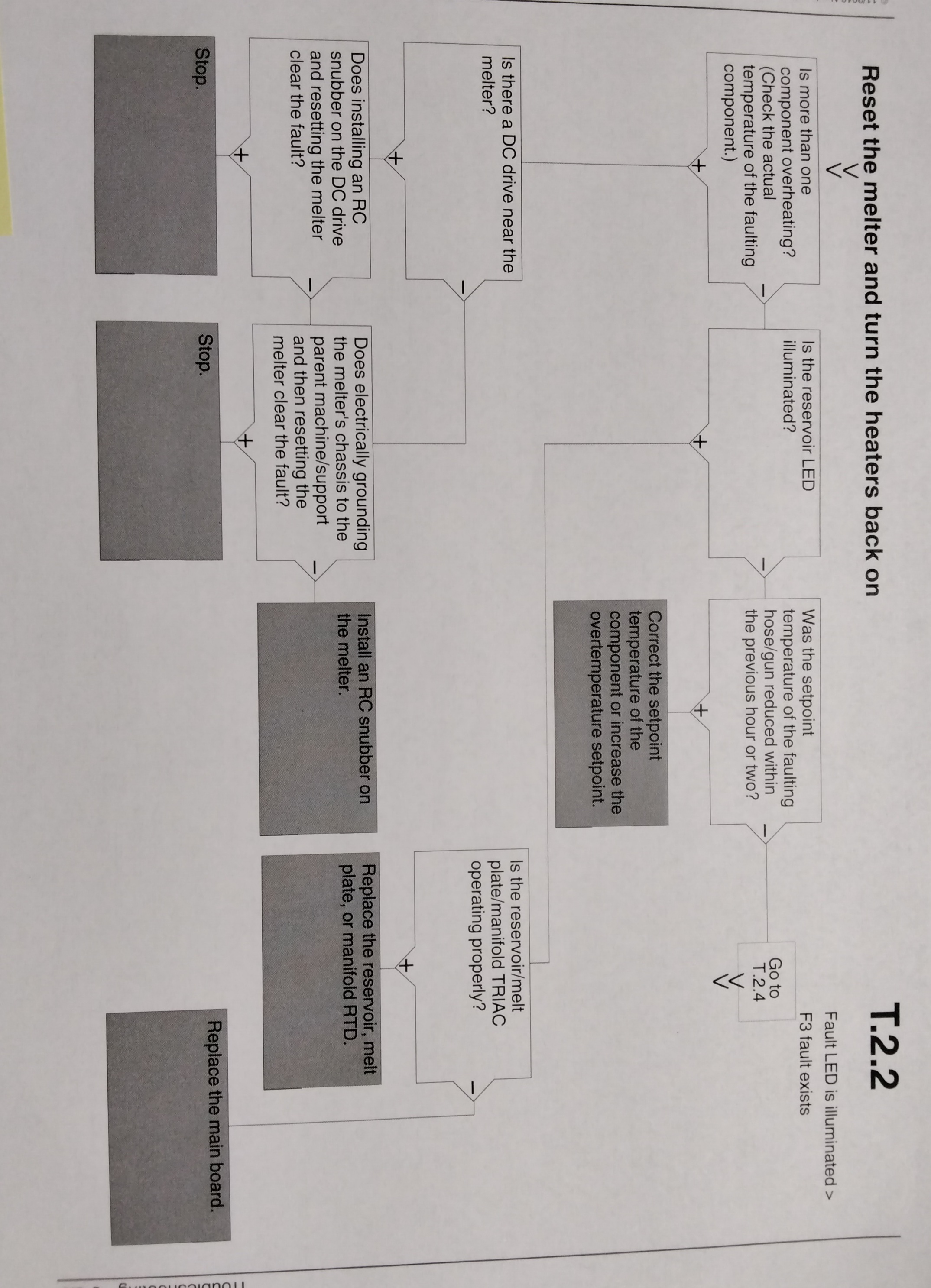
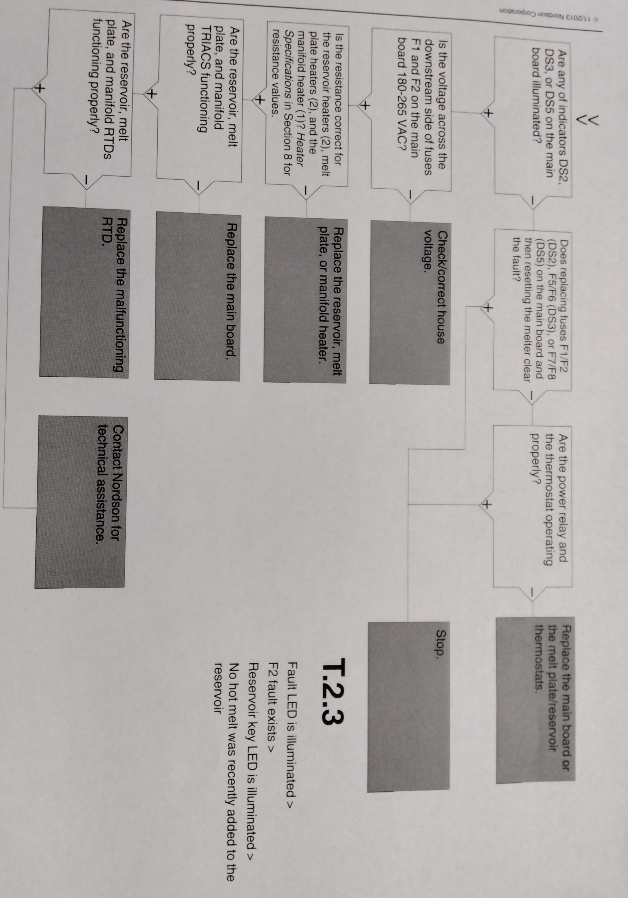
DISPLAY AFFECT ON CODE/ NAME MELTER CAUSE CORRECTIVE SUBCODE ACTION F1/None RTD Heaters turn The RTD for the Replace RTD off component indicated has Check hose/gun failed or the connections component was disconnected See flowchart from the melter. T-2 F2/None Under Temp Heaters The actual temp Check for conditions turn off of component that may cause a indicated has drop in ambient dropped below temperature. the under temp Delta, which was Replace RTD set using parameter 22. See Chart T.2 F3/None Over Temp Heaters The actual temp of Change parameter turn off component has 21. If problem increased above persists, replace the over temp RTD. delta, set in See Chart T.2 Parameter 21. F4/1 RAM test Melter stops Internal RAM failure Replace CPU functioning F4/2 Internal clock Heaters remain Internal clock failure Replace CPU Time on, but fault conditions persist. F4/3 RAM Backup Clock does not Insufficient voltage Replace CPU Battery function from RAM backup battery F4/4 Internal clock Heaters remain Battery-backed Replace CPU battery backed on, but fault RAM failure RAM condition persists
DISPLAY NAME AFFECT ON CAUSE CORRECTIVE CODE/ MELTER ACTION SUBCODE F4/5 Internal clock Heaters remain Battery backed Replace CPU battery on, but fault RAM condition battery dead persists F4/6 Analog to Melter stops RTD Analog to Replace main digital functioning digital converter board or CPU failed F4/7 Analog to Melter stops Failed hose or gun Replace hose or digital functioning RTD analog to digital gun, NOTE: Set calibration converter could setpoint to not be calibrated zero to avoid (grounded RTD in F1 fault system) F4/8 Main board Melter stops Communication failure Replace main feedback functioning between main board board, ribbon and CPU cable or CPU F4/A Thermostat Melter stops Reservoir or Replace Thermo- functioning melting plate stat, XP6 harness, thermostat is or main board open F4/C Expansion board Melter stops Ribbon cable P/N Check the ribbon connection functioning 1026662 is not cable connections connected at J1 and make on the main board connections and/or at J2 on the as applicable expansion board. F4/D Communications Heaters remain Communication Replace the I/O card with optional I/O on, but fault failure between or CPU card condition CPU and the persists optional I/O card F4/E Fieldbus Alert output (if Fieldbus card Replace the Fieldbus communications output option 6 failure card. failure is selected) Melter continues to operate normally
TROUBLESHOOTING MELTER FAULTS Table 6-1 3.
DISPLAY AFFECT ON CODE/SUBCODE NAME MELTER CAUSE CORRECTIVE ACTION F9/1 Reservoir Pump turns Reservoir empty Ensure that adhesive (See NOTE A) empty off and fault then pump present in the hopper output is continues to and allow time for the generated, but turn the number adhesive to melt into heaters and of rotations set the reservoir. Unless READY light in motor control it is critical that the unit remain on. parameter dLy turn off immediately (refer to Table when the reservoir is 3-11) empty, set the dLy value higher to prevent this fault condition. S1Cal Sensor Melter enters a continuous Check the S1 Sensor (See Note B) 1 standby melt plate-on calibration (refer to calibration mode condition ("Calibrating the Level occured Sensors" in Section 5. because the Maintenance) or adjust setting for the setting for para- parameter 49 meter 49. was exceeded (refer to Table 3-11) NOTE: A. An F9/1 fault does not create a fault condition, but it does generate a fault output. This output is visible only if the digital fault output or optional light tower are being used and is the only situation in which both a red and green light may be on at the same time. In such cases, the heaters and motor are okay, but the melter will not run because there is no adhesive in the reservoir. B. For a detailed description of how the melt-on-demand functionality of this melter works, refer to "Modes of Operation" in Section 2, "Introduction"
TROUBLESHOOTING MOTOR/PISTON CONTROL FAULTS 1
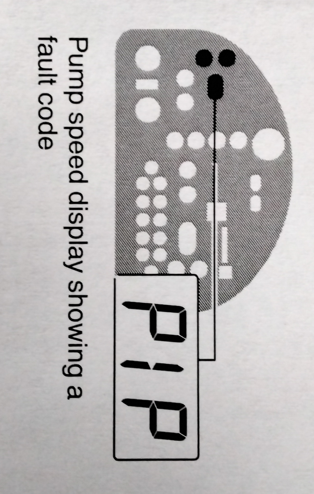
FAULT AFFECT ON POSSIBLE CORRECTIVE MELTER CAUSE ACTION diS (pump disabled Pump and heaters Reservoir empty Ensure that ad- turn off; F9/1 melter but pump con- hesive is present fault code displayed tinues to turn the in the hopper and on right display number of rotations allow time for the set in motor control adhesive to melt parameter dLy (refer into the reservoir to "Setting up the Unless it is critical Motor Control" that the unit turn Section 3 off immediately "Installation" when the reservoir is empty, set the dLy higher to prevent this fault condition. FLt (Motor Motor turns off Motor cable discon- Ensure that motor Thermostat nected or motor cable is connected. Fault) temp to high Ensure that motor is not operating above maximum rpm, hydraulic pressure, or ambient temperature. No P1P (Lid Piston cannot Lid is not Closed Close the lid. not closed) be lowered N/A Display rpms do Pump speed Calibrate the pump not match motor display not speed display. Refer to speed calibrated "Calibrating the Pump Speed Display" in Section 5, "Maintenance"
TROUBLESHOOTING MOTOR/PISTON FAULTS 2
FAULT AFFECT ON POSSIBLE CORRECTIVE MELTER CAUSE ACTION N/A Motor control Improper motor Check motor not operating control parameter control parameter as expected settings settings. Refer to "Setting Up the Motor Control" in Section 3 "Installation" N/A Piston stuck in excessive downward Press the PISTON UP down position air pressure (Greater key , increase the than 2 bar (30psi) on piston air pressure a slug or foil bag torn to the maximum, or damaged. and wait 5 minutes. If after 5 minutes the piston has not lifted, increase the melter temperature to the maximum safe limit recommended by the material supplier. Allow the temperature to stabilize for 30 min. (with the maximum air pressure still applied)
TROUBLESHOOTING MOTOR DRIVE FAULTS Table 6-3 1
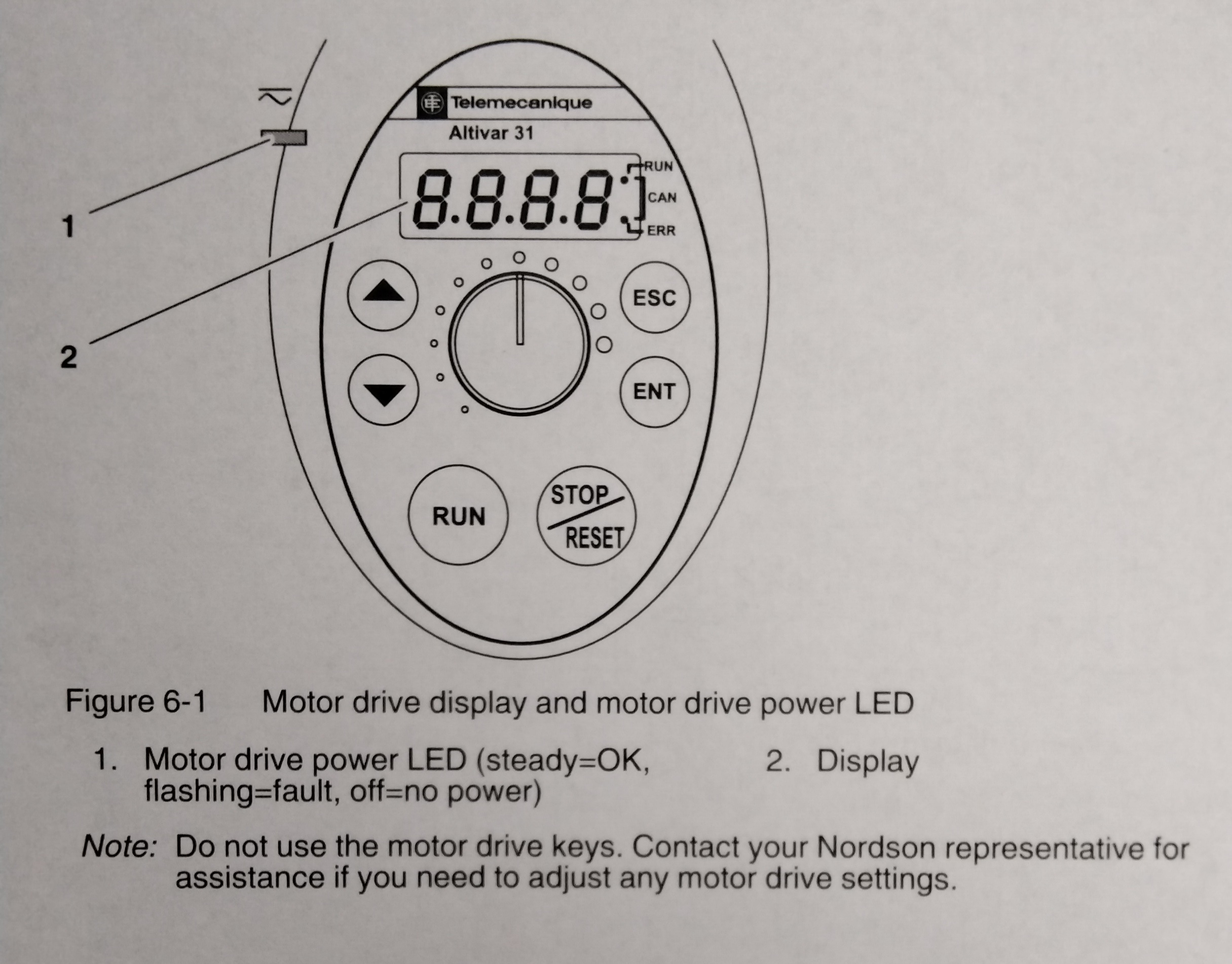
The display on the motor drive located inside the electrical enclosure alerts the operator to abnormal motor drive/motor operation. Motor drive faults cause the pump to stop. Refer to Table 6-3 for the motor drive fault codes. To clear a motor drive fault, correct the problem that caused the fault and then remove power from the motor drive by turning the heaters off. Wait until the motor drive display is completely blank. FAULT PROBABLE CORRECTIVE CODE CAUSE ACTION CrF Motor drive hardware Replace the motor Capacitor Failure drive load circuit EEF EEPROM Internal memory -Check the environment fault fault (electromagnetic compatibility) - Replace motor drive InF Internal fault - Check the environment Internal fault (electromagnetic com- patibility). - Replace the motor drive. OCF -Adhesive too cold -Verify temp setpoints and Overcurrent - Pump or drive change as needed. The failure temp. setpoints should -Foreign object in be within the range re- pump commended by the material manufacturer. - Replace the pump or the drive assembly. -Replace the pump. SCF Motor Short-circuit or earthing - check cables between the short-circuit at the motor drive motor drive and the motor; output also check the motor insulation. OHF Motor Motor drive temp too -Check the motor load, the drive over- high motor drive ventilation, and heated the environment. Wait for the motor drive to cool down before restarting. -Ensure that the unit ambient temperature does not exceed 50 degrees C (120 F), that the electrical enclosure vents are not blocked, and that the electrical enclosure vents are not blocked, and that the electrical enclosure fan is operating properly.
TROUBLESHOOTING MOTOR DRIVE FAULTS Table 6-3 2
FAULT PROBABLE CORRECTIVE CODE CAUSE ACTION OLF - Material exceeds - Use a material that motor the operating falls within the overload viscosity range allowable viscosity - Excessive motor range. Refer to current Section 8,"Technical - Over pressure ranges. condition caused - Check the motor load. by PCV failure wait for the motor drive to cool down before restarting. - If the operating hydraulic pressure exceeds the maximum allowable pressure, replace the PCV. Refer to Section 8 "Technical Data" for allowable input voltage range. OPF motor Loss of one or more - Check the connections phase loss phases at motor between the motor drive drive output. and the motor. OSF Over- -Line voltage too high Check the unit input line voltage - Disturbed line voltage. Refer to Section 8, supply. "Technical Data", for allowable input voltage range. CFF Motor drive parameter(s) Contact your Nordson Configuration changed representative. Fault USF under -Line supply too low Check the unit input line voltage -Transient voltage dip voltage. Refer to Section 8, "Technical Data, for allowable input voltage range.
TROUBLESHOOTING PUMP OPERATIONAL STATUS Table 6.4 1
NOTE: To use the pump operating variables table, ensure that the PUMP MODE key LED is on and that motor speed is at a setting other than 0. In addition, ensure that the reservoir is not empty. When diagnosing apparent melter malfunctions, it is helpful to understand the following variables that control the status of the pump (enabled or disabled) and the associated indication that is provided by the pump LED. - Use/activation of a remote input to control the motor. - Use a parameter 8, "Automatic Pump On" -Ready status of the melter. - Activation of a switched input (handgun or footswitch) - Activation of the pump key Table 6-4 provides the status of the pump LED for each combination of the pump operating variables.
TROUBLESHOOTING PUMP OPERATIONAL STATUS Table 6.4 PUMP OPERATING VARIABLES 2
Pump Remote Remote Automatic Handgun/ Handgun/ Unit Pump Motor LED Motor Motor Pump On Footswitch Footswitch Ready Key Rotating Status Input Input (Parameter 8) input Status Press assigned Status status Status (see (see (see Note Note Note A) B) C) ------------------------------------------------------------------------------------------------------ Single Not N/A Disabled Not N/A No Ignored No green Assigned present flash, then off Off Not N/A Disabled Not N/A Yes Off No Assigned present Green Not N/A Disabled Not N/A Yes On Yes Assigned present Off Not N/A Enabled Not N/A No Off No Assigned present Yellow Not N/A Enabled Not N/A No Off No Assigned present Off Not N/A Enabled Not N/A Yes Off No Assigned present Green Not N/A Enabled Not N/A Yes On Yes Assigned present Single Not N/A Disabled Present On/Off No Ignored No green Assigned flash then off Off Not N/A Disabled Present On/Off Yes Off No Assigned Yellow Not N/A Disabled Present Off Yes On No Assigned Green Not N/A Disabled Present On Yes On Yes Assigned Off Not N/A Enabled Present On/Off No Off No Assigned Yellow Not N/A Enabled Present On/Off Yes On Yes Assigned Off Not N/A Enabled Present On/Off Yes Off No Assigned Green Not N/A Enabled Present On Yes On Yes Assigned Yellow Not N/A Enabled Present Off Yes On No Assigned Single Assigned On/Off Disabled Not N/A No Ignored No Green Present Flash then off Off Assigned On Disabled Not N/A Yes Off No Present Flashing Green Assigned Off Disabled Not N/A Yes On
TROUBLESHOOTING PUMP OPERATIONAL STATUS Table 6.4 PUMP OPERATING VARIABLES 3.
Pump Remote Remote Automatic Handgun/ Handgun/ Unit Pump Motor LED Motor Motor Pump On Footswitch Footswitch Ready Key Rotating Status Input Input (Parameter 8) input status Status Press assigned Status Status (see (see (see Note Note Note A) B) C) -------------------------------------------------------------------------------------------------- Green Assigned On Enabled Not N/A Yes On Yes Present NOTE A: If any of Parameters 30-39 are set to 3 or 11, then the remote motor input is assigned. B: If the remote motor input is assigned, then its status is described in this column. C: "On" means the pump key was pressed and the unit accepted the key pass. "Ignored" means that the pump key will not respond to a key press.
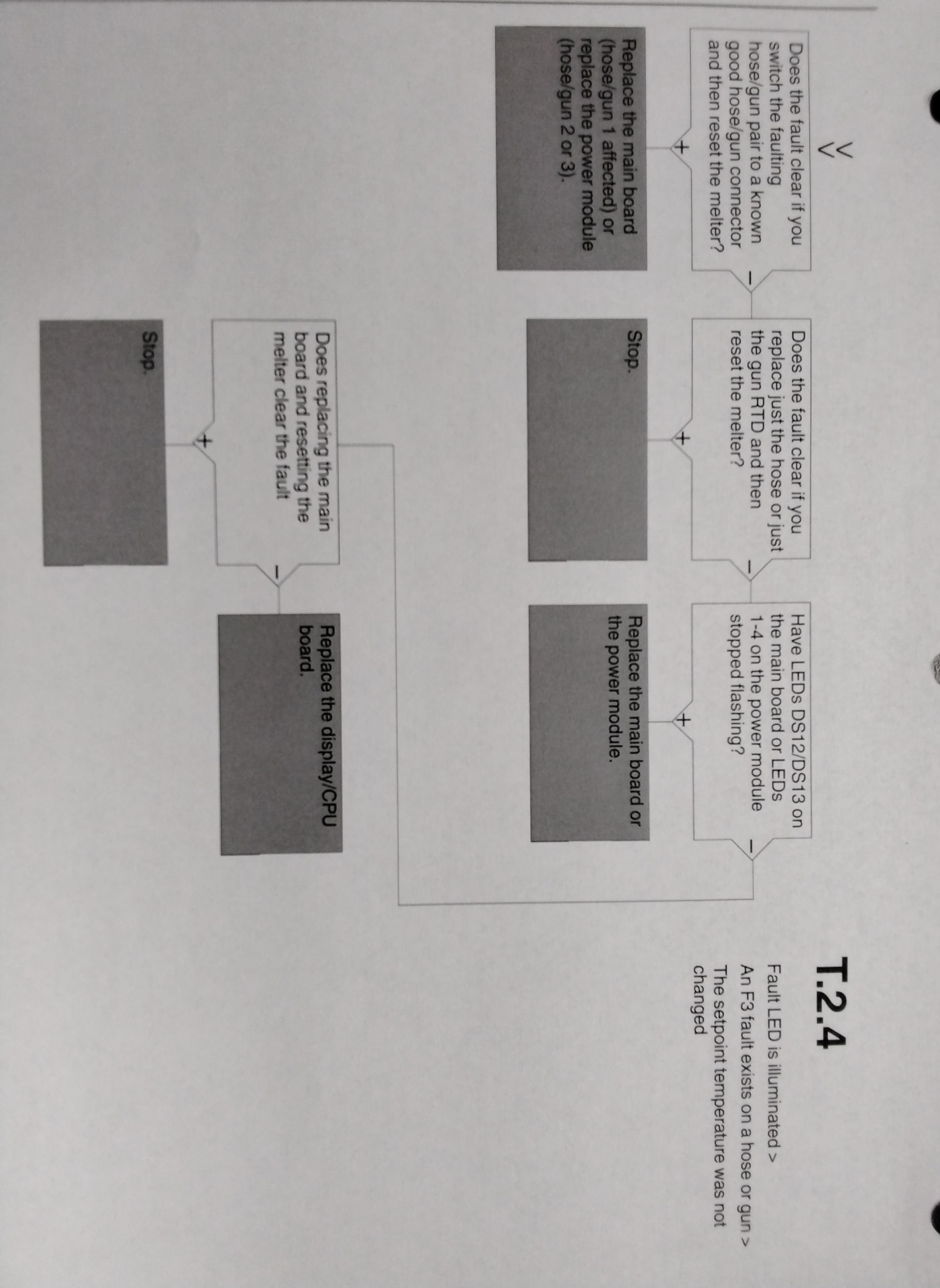
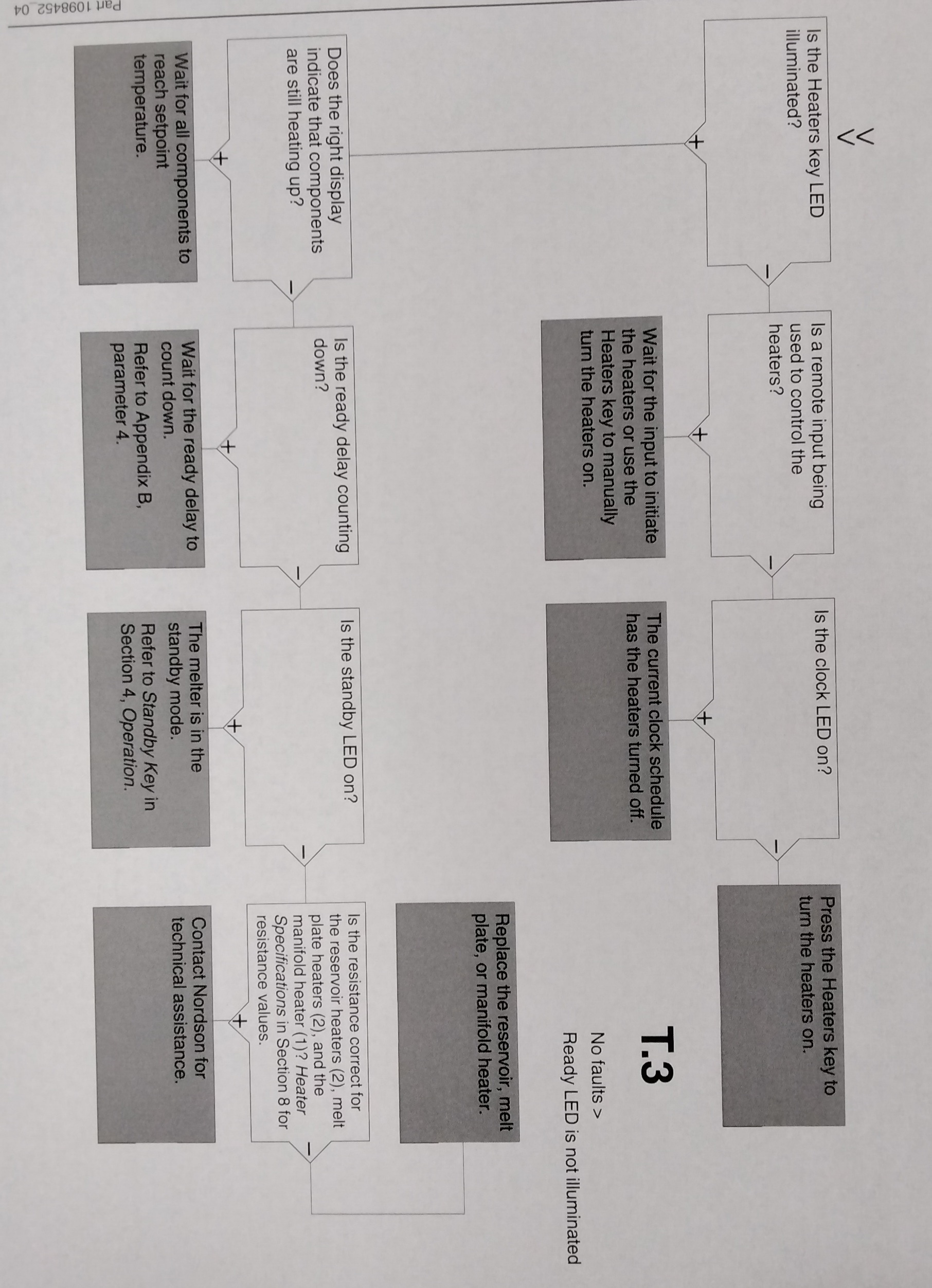
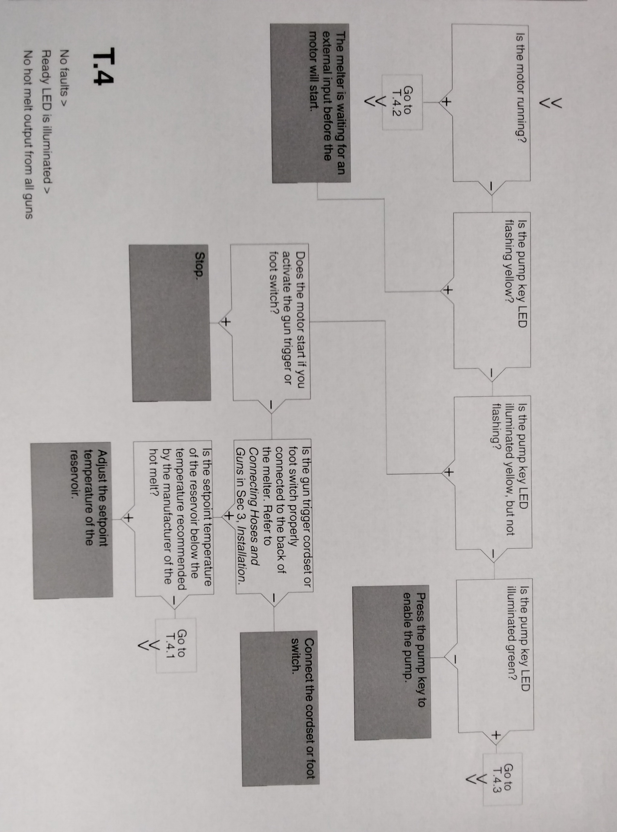
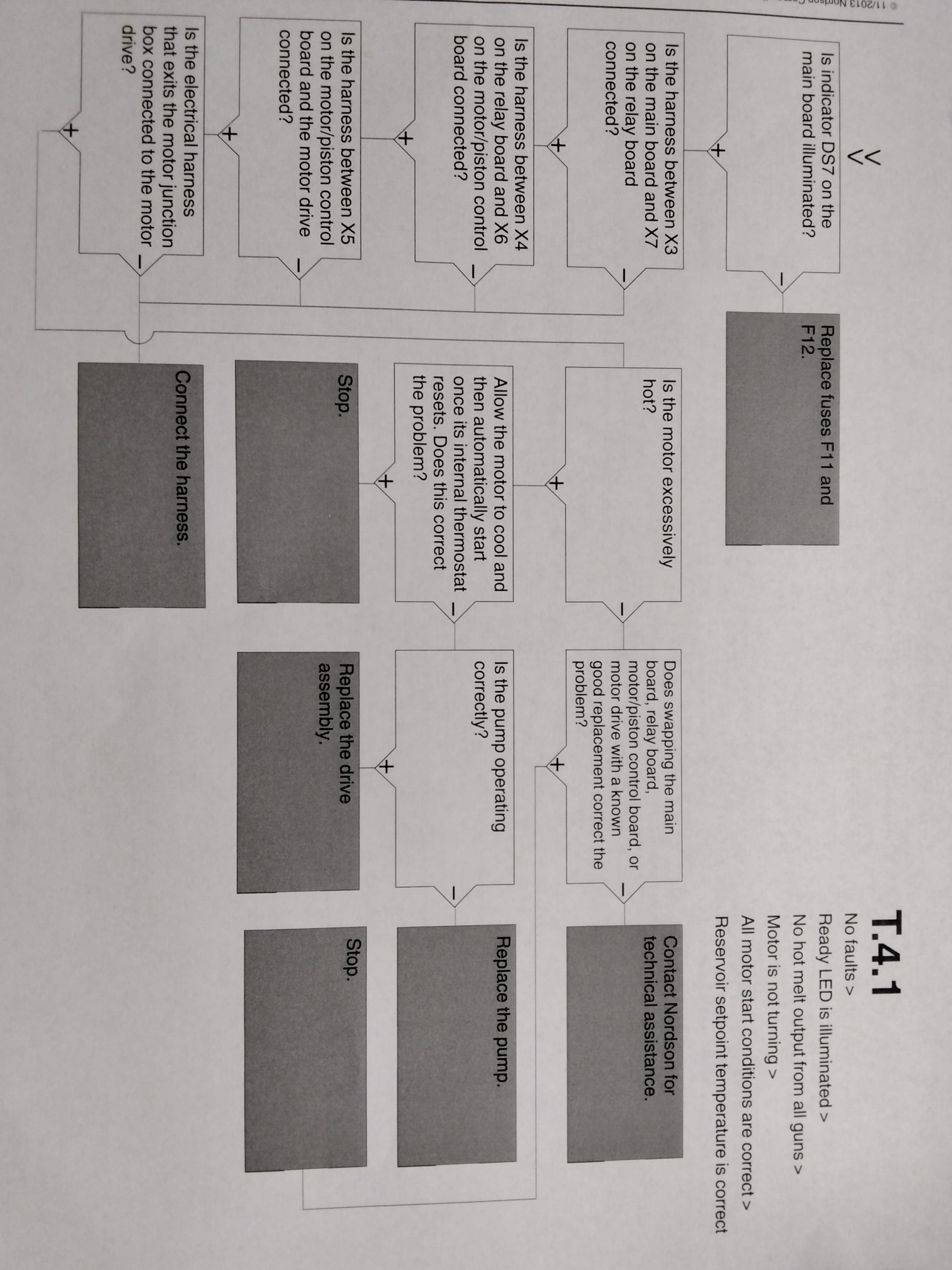
USING THE TROUBLESHOOTING FLOW CHART
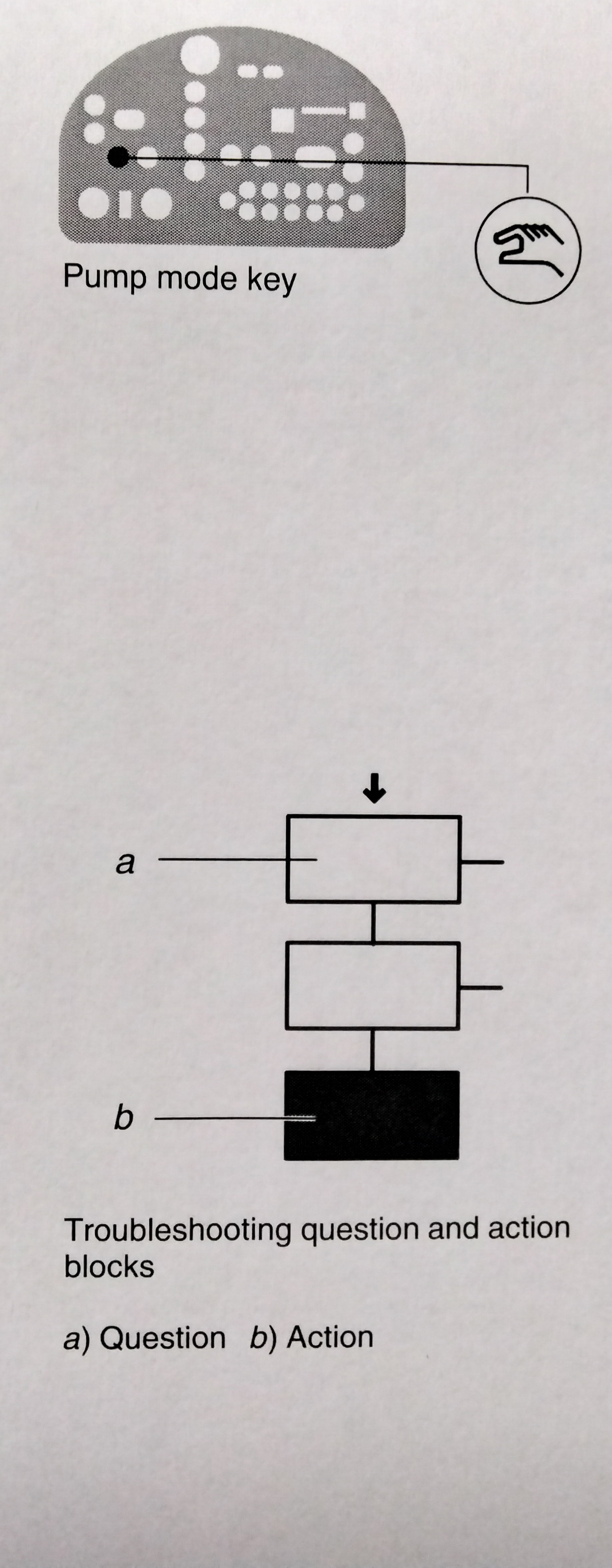
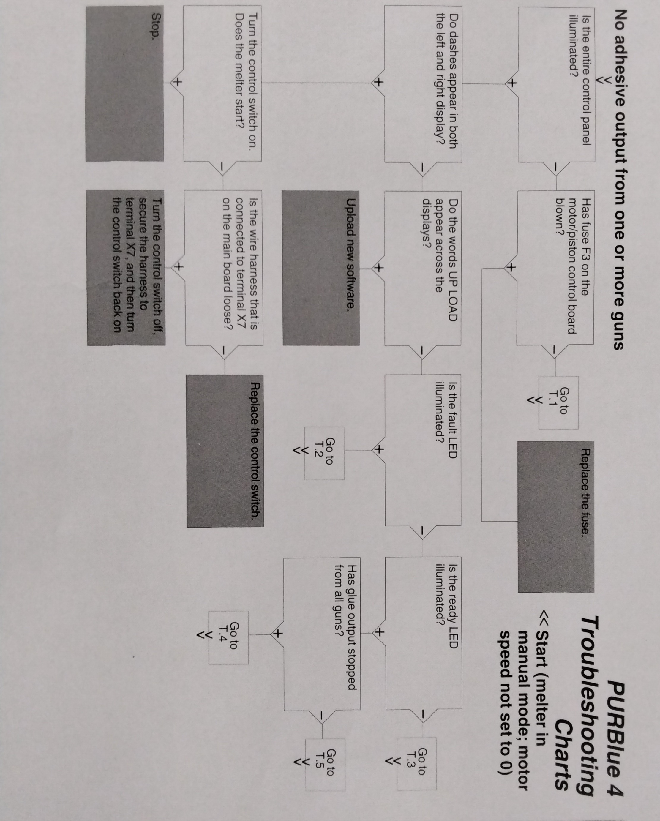
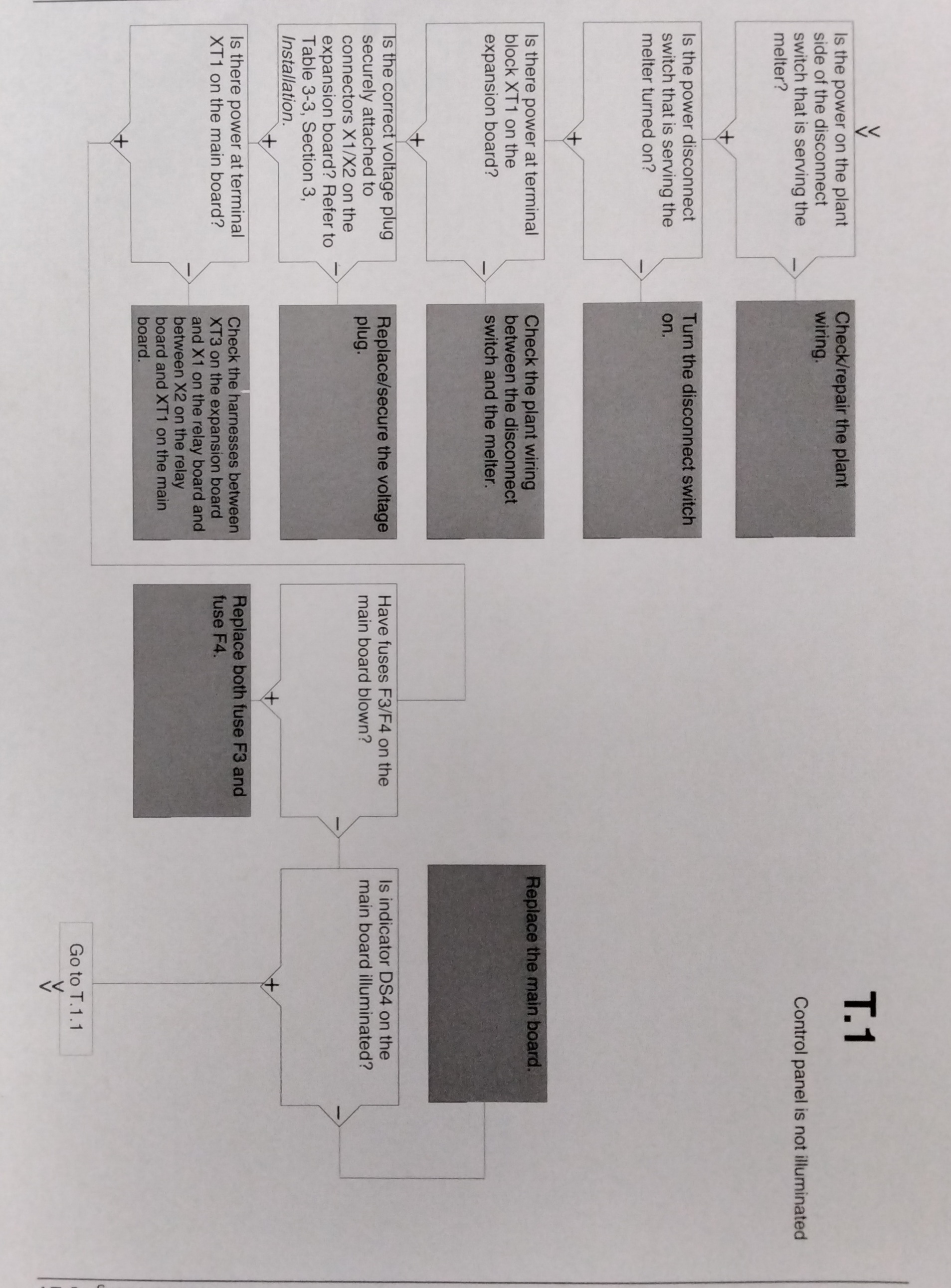
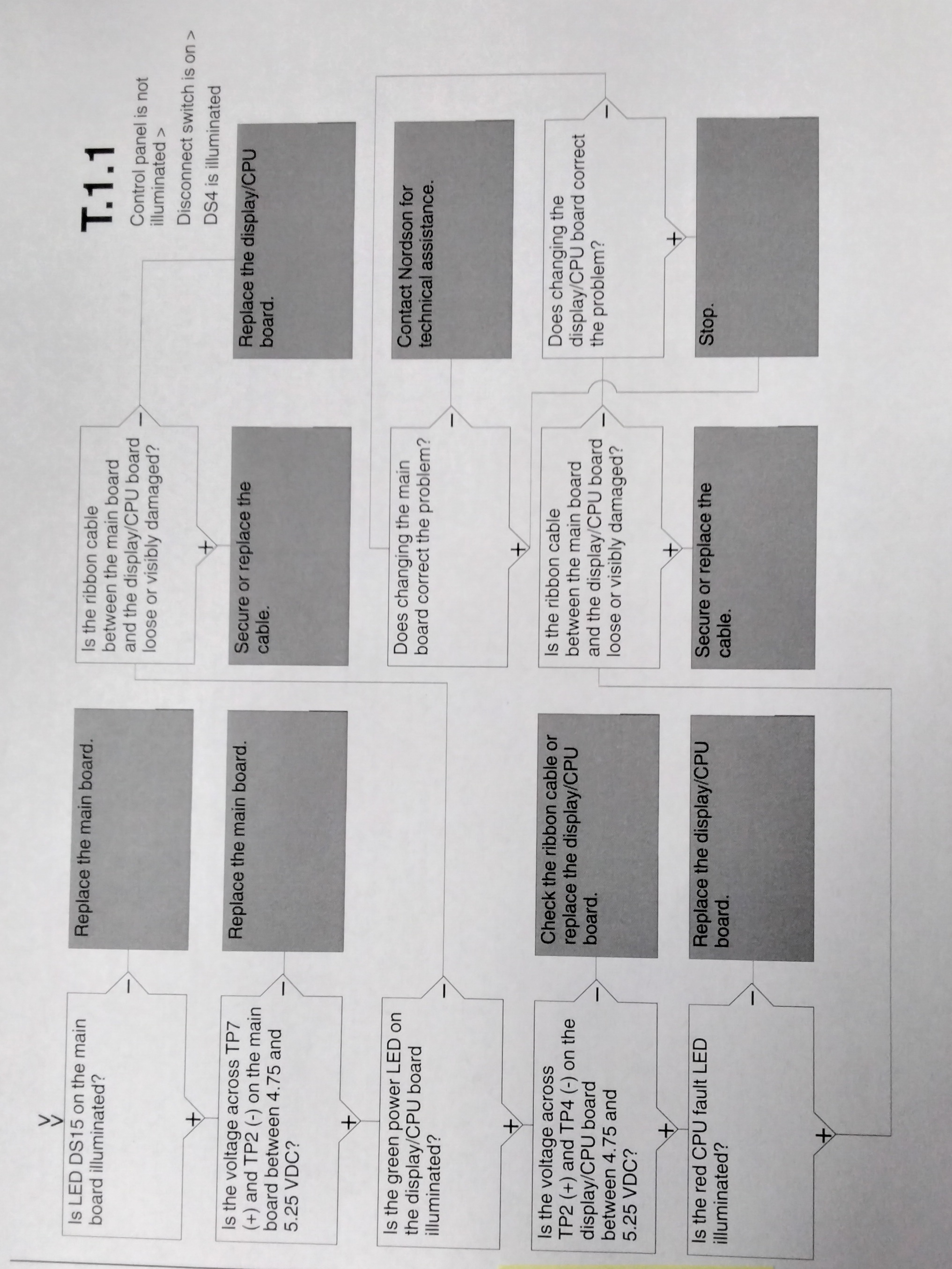
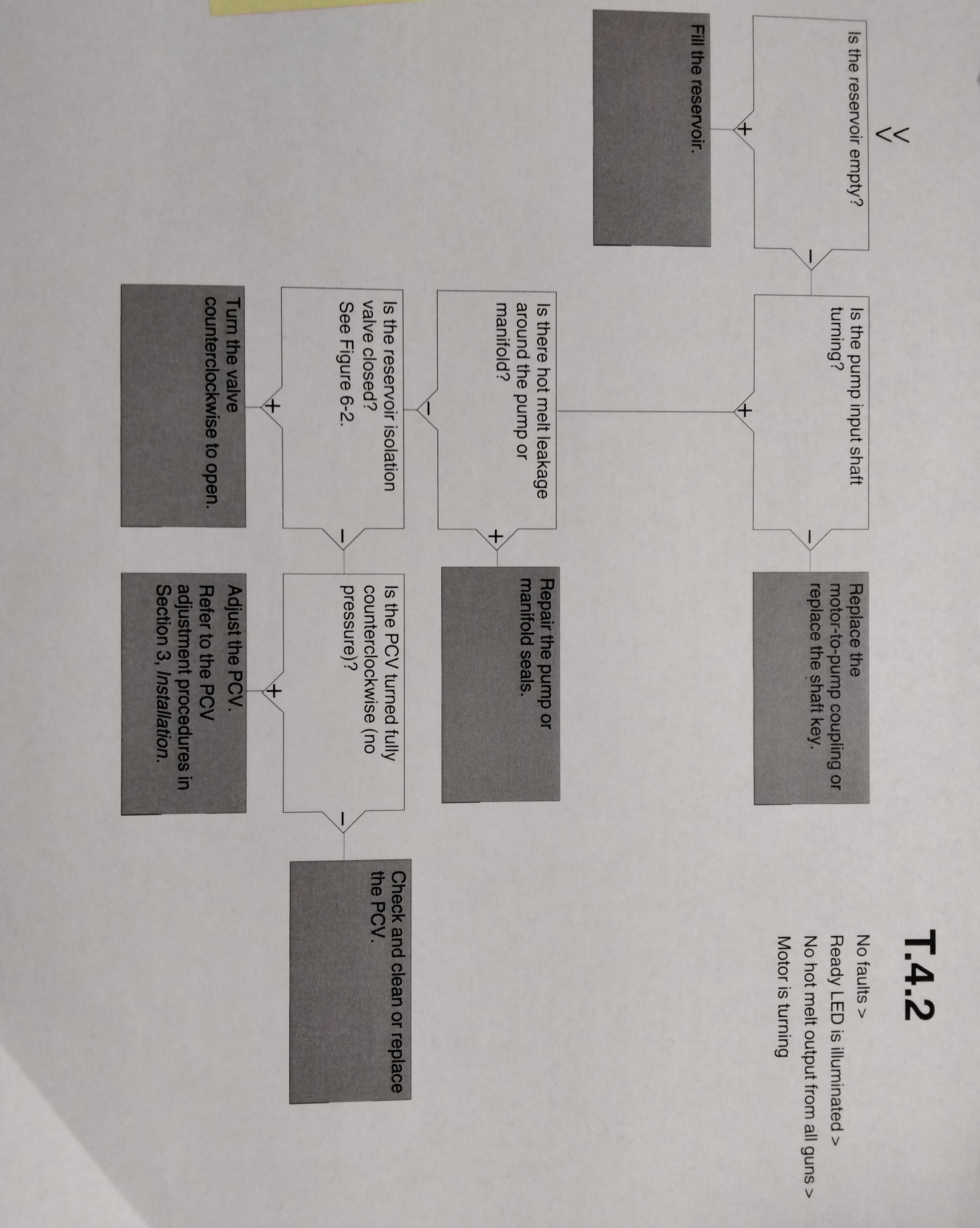
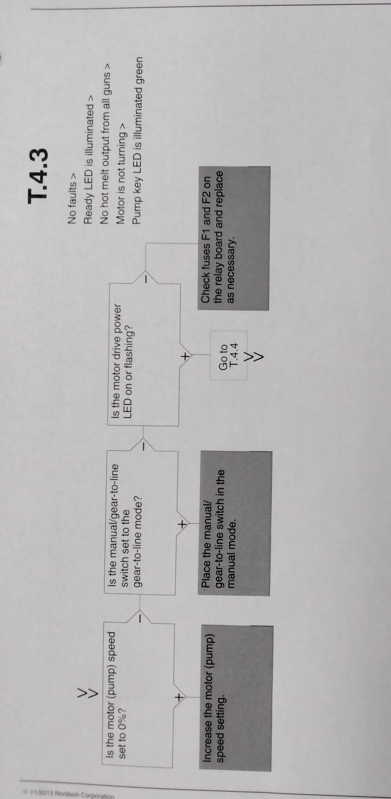
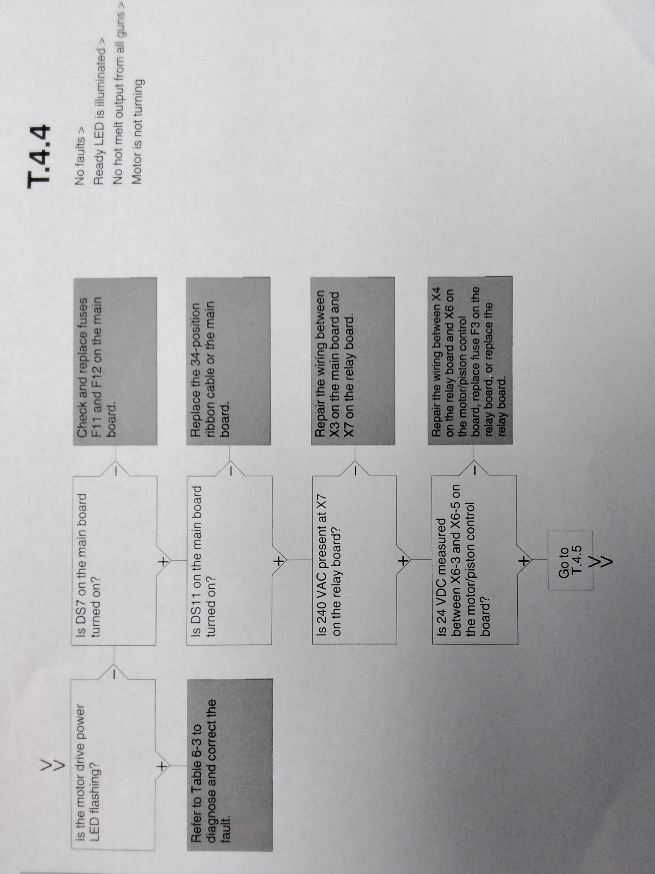
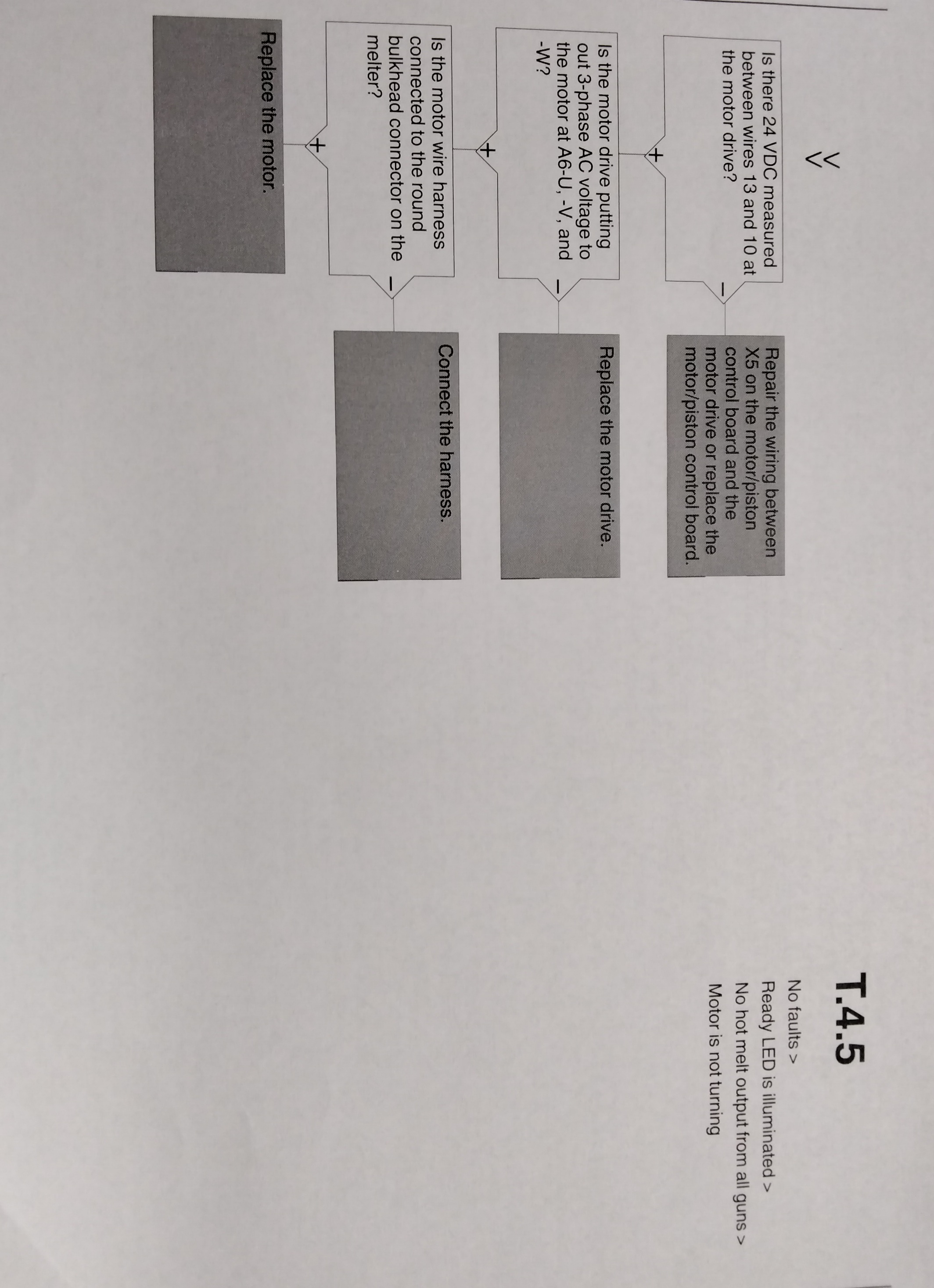
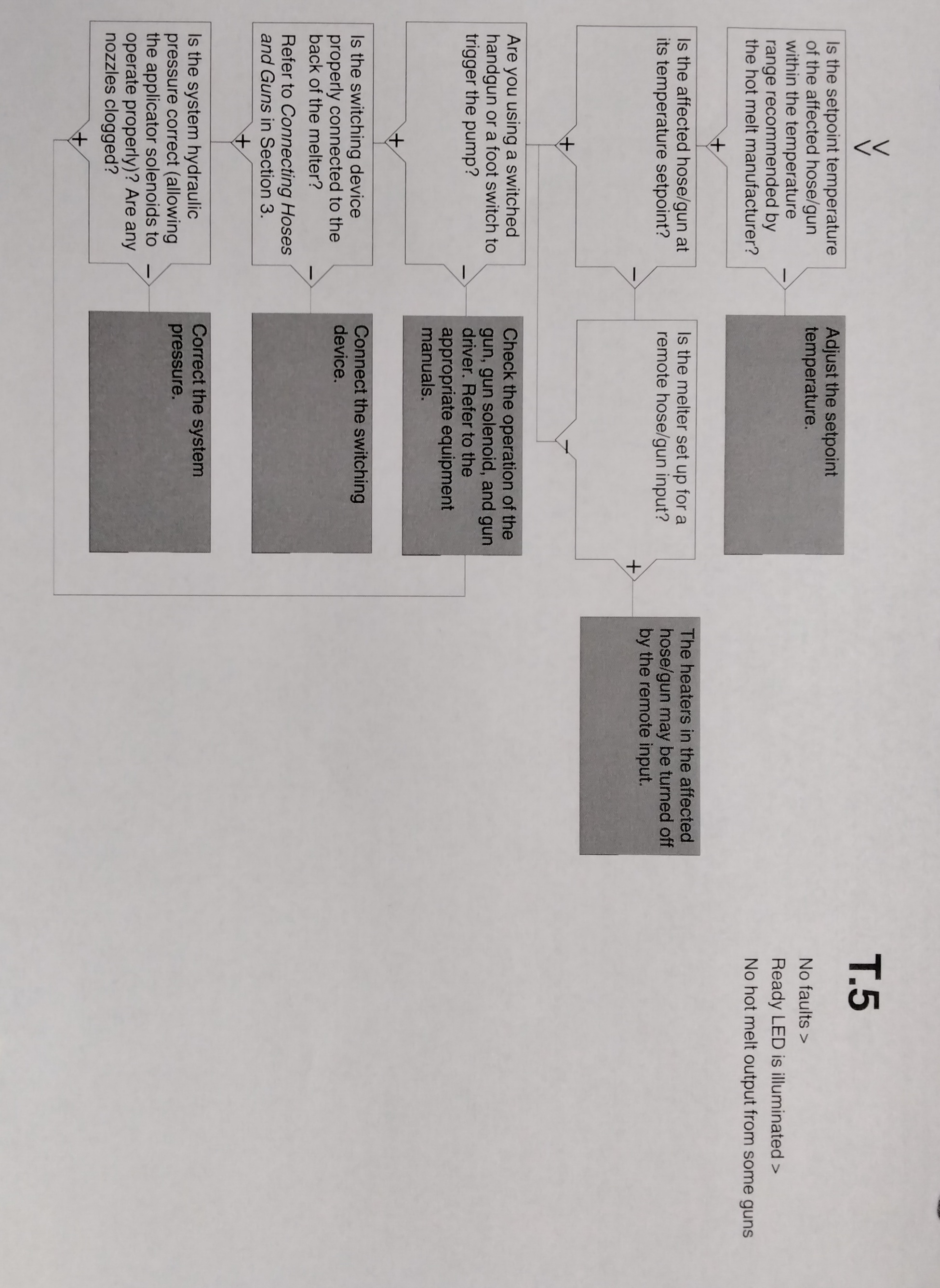
NOTE: To use the pump operating variables table, ensure that the PUMP MODE key LED is on and that the motor speed is at a setting other than 0. In addition, ensure that the reservoir is not empty. The flowchart, which is provided at the end of this section, is designed to assist you in diagnosing and correcting a complete or partial stop in hot melt output from the guns. The chart is organized in a simple question-action block format. If your response to a question is yes (+), continue downward in the chart to the next question or action block. If your response is no(-), continue to the right to the next question or action block. All diagnostic paths within the chart end with an action block that specifies one of the following courses of action: - Refer to information provided elsewhere in this manual - Refer to component. To return your melter to service as quickly as possible, the chart is designed under the assumption that it is preferable to immediately replace a faulty assembly as opposed to conduction detailed diagnostics and repair of the assembly while the melter is out of service. Use of the chart assumes that the melter is installed correctly and that it is set up to support the current manufacturing process. Refer to Section 3, "Installation" for information about installing and setting up the melter.
TROUBLESHOOTING QUICK-CHECKS
Before using the troubleshooting charts confirm: - whether or not the service was recently performed on the melter or the melter's settings were recently adjusted. - the correct voltage plug is installed on connector X1 and/or X2. Refer to the Section 3, "Installation", for information about selecting the correct voltage plug. - External inputs (if used) are functioning properly. - the standby or clock functions are not turned on (if not required or expected at the current time).
TROUBLESHOOTING - RETURNING THE MELTER SETUP TO FACTORY SETTINGS
By returning the melter to its factory setting many common melter problems can be isolated to either a problem with the melter settings or the melter hardware. To return the melter to its factory settings, switch the melter off, simultaneously press the SETUP and RIGHT DISPLAY SCROLL DOWN keys, and then switch the melter back on, holding the SETUP and RIGHT DISPLAY SCROLL DOWN keys until the letters PUR appear on the right display. NOTE: If PUR does not appear upon a first attempt at factory reset, switch the melter back on, holding the RESERVOIR and CLEAR/RESET keys. and then switch the melter back on, holding the RESERVOIR and CLEAR/RESET keys until the letters PUR appear on the right display. This will reset the melter as a PUR melter.
TROUBLESHOOTING - IDENTIFYING ELECTRICAL COMPONENTS - Table 6-5 1
Tables 6-5 through 6-9 provide detailed descriptions of the circuit board indicators, connecting points, and test points that are referred to in the troubleshooting chart. Refer to the wiring diagram in Section 8, "Technical Data", for the location of each of these circuit board components. Table 6-5 MAIN BOARD COMPONENTS 1 ITEM TYPE DESCRIPTION NUMBER INDICATORS DS2 Neon Power to reservoir heater DS3 Neon Power to manifold heater DS4 Neon Power to 5VDC and 24 VDC power supplies DS5 Neon Power to melt plates DS6 Neon Power to hose/gun 1 heaters DS8 LED Control signal for melt plate heater DS9 LED Not used DS10 LED Control signal for reservoir heaters DS11 LED Control signal for motor DS12 LED Control signal for gun1 heater DS13 LED Control signal for hose 1 heater DS14 LED Control signal for manifold heater DS15 LED +5 VDC control voltage present DS17 LED Trigger closure present at XP4 or XP4 FUSES F1/F2 Reservoir heaters (10A, 250V, fast-acting) F3/F4 5VDC power supplies (2A, 250 V, slow-blowing) F5/F6 Manifold heater (5 A, 250 V, fast-acting 5X20 mm) F7/F8 Melt plate heaters (6.3 A, 250 V, 5X20 mm) F9/F10 Hose/gun 1 heaters (6.3 A, 250 V, 5X20 mm) F11/F12 Motor start (6.3A. 250 V, 5X20 mm)
TROUBLESHOOTING INDENTIFYING ELECTRICAL COMPONENTS - Table 6-5 2
Table 6-5 MAIN BOARD COMPONENTS 2 ITEM TYPE DESCRIPTION NUMBER Connection Points XT1 Input High-voltage power connection to board J1 Input/Output Signal ribbon cable between main board and CPU XP1 Output Control voltage to gun solenoid 1 XP2 Output Control voltage to gun solenoid 2 XP3 Input Switch to closure from handgun 1 XP4 Input Switch to closure from handgun 2 XP5 Input Manifold RTD XP6 Input Reservoir RTD and reservoir over temperature thermostat. X1 Output High-voltage tp manifold heater X2 Output High-voltage tp reservoir heaters X3 Output High-voltage to motor X4 Output High-voltage and control voltage out to melt plate heaters X5 Output High-voltage and control voltage out to hose/gun 1 X6 Output 24 VDC to expansion board X7 Input Unit On/Off control switch Test Points TP7 Contact +5 VDC control voltage present TP2 Contact Circuit common of low-voltage power supply
TROUBLESHOOTING IDENTIFYING ELECRICAL COMPONENTS - Table 6-6 EXPANSION BOARD COMPONENTS
ITEM TYPE DESCRIPTION NUMBER Indicators DS1 LED 24 VDC present at X3 Connection Points XT1 Input AC power into board XT2 Output AC power out to power module (hoses/guns 2 and 3) XT3 Output AC power out to power main board. XT7 Output/Input Positions 1-6 are control outputs; position 7-14 are control input. X1/X2 Jumper Input voltage configuration plugs X3 Input 24 VDC in from main board X4 Input/Output Ribbon cable connection between expansion board and power module (hoses/guns 2 and 3) J2 Input/Output Ribbon cable connection between expansion board and main board.
TROUBLESHOOTING IDENTIFYING ELECTRICAL COMPONENTS Table 6-7 POWER MODULE COMPONENTS
ITEM TYPE DESCRIPTION NUMBER Indicators N1 Neon Hose 3 is turned on N2 Neon Gun 3 is turned on N3 Neon Hose 2 is turned on N4 Neon Gun 2 is turned on Connection Points J1 Input/ Output Ribbon cable connection between power module and expansion board J2 Input/ Output Connection point for the wire harness between hose/gun 3 and the power module. J3 Input/Output Connection point for the wire harness between hose/gun 2 and the power module. J4/J5 Input AC power input from XT2 on the expansion board Fuses F1, F2 Hose 3 and gun 2 F3. F4 Hose 2 and gun 2
TROUBLESHOOTING IDENTIFYING ELECTRICAL COMPONENTS Table 6-8 PISTON/MOTOR CONTROL BOARD COMPONENTS
ITEM TYPE DESCRIPTION NUMBER Indicators DS5 LED Status DS7 LED Reservoir empty DS8 LED Motor enable input DS9 LED Piston in place DS10 LED Melt on demand DS12 LED Hopper empty DS15 LED Motor thermostat DS16 LED Power switch on DS14 LED Serial port fault Connection points X1 Input/Output Expansion serial port connection X2 Input/Output Serial port connection to melter CPU X3 Data CPU debug connector X4 Input Membrane key pad X5 Signal Input/Output Connections to motor drive X6 Signal Input DIN Rail board connections X8 Signal Input/Output Melter I/O connections X9 Signal Input/Output Power switch connection X10 Signal Output Membrane panel LEDs TB1 Output Piston solenoid connections TB4 Sensor input Piston-in-place sensor connection TB5 Sensor input Melt on demand sensor connection TB6 Sensor input Reservoir empty sensor connection TB7 Sensor input Hopper empty sensor connection SW1 Switch Switch to put motor control CPU into software upgrade mode.
TROUBLESHOOTING IDENTIFYING ELECTRICAL COMPONENTS Table 6-9 RELAY BOARD COMPONENTS
ITEM NUMBER TYPE DESCRIPTION Connection points X1 Input Power X2 Output Power X3 Output Motor drive and 24V power supply X4 Output Motor piston control X5 Input Customer-supplied motor run-up input signal X6 Output 240V fan power (Option C) X7 Input Motor relay power X8 Input 24 VSC power to board J1 Input Solenoid signals from main board J2 Test Test J3 Test Test J4 Output Solenoid 1 J5 Output Solenoid 2 Fuses F1 Fuse Fuses for fan, motor drive, 23VDC power suply F2 Fuse Same as above F3 Fuse Fuse for 24 VDC power to and through board
TROUBLESHOOTING CHARTS
Source: Ideal Cabinetry (Community Member)

